
Shielded High Flex Cable for EMI Protection
Introduction: The Growing EMI Challenge in Modern Automation Electromagnetic interference (EMI) has become one of the most pervasive—and expensive—reliability challenges in modern industrial automation. The proliferation of variable frequency drives (VFDs), switching…
Introduction: The Growing EMI Challenge in Modern Automation
Electromagnetic interference (EMI) has become one of the most pervasive—and expensive—reliability challenges in modern industrial automation. The proliferation of variable frequency drives (VFDs), switching power supplies, wireless communication systems, and high-speed digital controllers has created electromagnetic environments that would have been unimaginable just two decades ago.
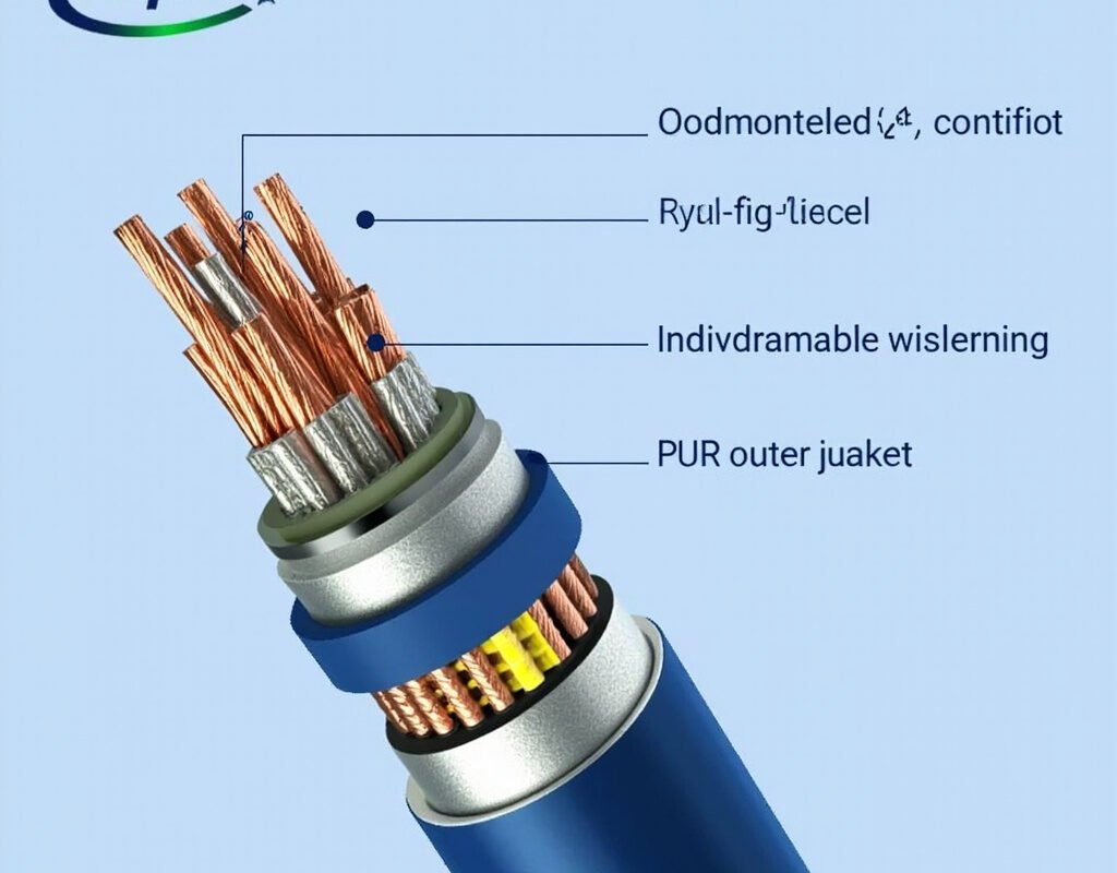
Shielded high flex cable solutions form the primary defense against this invisible threat. A properly specified EMI resistant flex cable can mean the difference between a stable production cell and one plagued by mysterious sensor glitches, intermittent communication dropouts, and unexplained safety system trips.
This guide provides the engineering depth needed to design effective EMI protection into your flexible shielded cable infrastructure—covering everything from the physics of shielding effectiveness to practical grounding strategies and real-world troubleshooting.
Understanding EMI Sources in Industrial Environments
The Noise Spectrum: What We’re Fighting Against
Industrial EMI spans an extraordinarily wide frequency range:
| Source | Frequency Range | Typical Amplitude | Coupling Mode |
|---|---|---|---|
| VFD switching (IGBT) | 2–50 kHz fundamental; edges to MHz | Hundreds of amps peak | Conducted + radiated near-field |
| VFD output PWM carrier | 2–16 kHz carrier; edges to 10 MHz+ | Motor current level | Radiated from motor cables |
| Switch-mode power supplies | 50 kHz–5 MHz switching | Varies by power level | Both conducted and radiated |
| Radio frequency interference | 100 kHz – 6 GHz | mV to V-level (field strength) | Radiated far-field |
| Electrostatic discharge (ESD) | Sub-nanosecond edge, broadband | kV-level transients | Direct coupling or field induction |
| Welding arc ignition | 2–4 MHz start pulse | kV-level transients | Radiated near-field |
| Wireless devices (WiFi, BT) | 2.4 GHz / 5 GHz bands | mW to W transmit | Radiated far-field |
How EMI Damages Control Systems
Conducted EMI enters systems through:
- Power supply inputs (coupling through input filters)
- Signal I/O ports (direct conductor injection)
- Shield penetration at imperfect terminations
- Ground reference shifts between interconnected equipment
Radiated EMI couples via:
- Magnetic field pickup in loop antennas (cable pairs forming loops)
- Electric field coupling to unshielded conductors
- Slot leakage in enclosures (cable penetrations act as slot antennas)
Symptoms of inadequate shielded high flex cable**:
- Analog signal noise: Erratic readings on sensors (temperature, pressure, position) — ±5% or worse fluctuation
- Digital communication errors: CRC errors, retransmissions, timeouts on fieldbus networks
- Encoder count loss: Missing pulses causing position drift or velocity ripple
- Safety system nuisance tripping: E-stop circuits falsely triggering; safety gate monitors showing faults
- PLC/Drive fault codes: “Communication loss,” “Encoder error,” “Overvoltage” without apparent cause
- Motor heating: Common-mode currents circulating through motor bearings (bearing fluting damage)
Shielding Physics and Effectiveness Metrics
Transfer Impedance: The Gold Standard Metric
The most meaningful measure of shield performance is transfer impedance (Z_T):
Z_T = V_shield / I_shield   [Ω/m]

Where:
  V_shield = voltage induced on inner conductor surface per unit length
  I_shield = current flowing on shield outer surface

Lower Z_T = better shielding performance
Typical Z_T values by shield type at key frequencies:
| Shield Type | Z_T @ 1 MHz | Z_T @ 10 MHz | Z_T @ 100 MHz |
|---|---|---|---|
| Single braid (85% coverage) | 5–20 mΩ/m | 10–50 mΩ/m | 20–100 mΩ/m |
| Double braid (95% total) | 1–5 mΩ/m | 2–10 mΩ/m | 5–20 mΩ/m |
| Foil + braid combination | 0.5–3 mΩ/m | 1–5 mΩ/m | 2–10 mΩ/m |
| Serve/spiral wrap | 10–30 mΩ/m | 20–80 mΩ/m | 50–200 mΩ/m |
Practical interpretation: For double shielded high flex cable, expect transfer impedance of 1–5 mΩ/m at 1 MHz—meaning that for every ampere of interfering current on the shield, only 1–5 millivolts appears across the internal conductors per meter of cable length.
Shielding Effectiveness (SE) in Decibels
Shielding effectiveness is often expressed logarithmically:
SE(dB) = 20 × log₁₀(E_field_without_shield / E_field_with_shield)

Or equivalently: SE(dB) = 20 × log₁₀(Z_open_circuit / Z_T)

Where higher dB values = better shielding:
  20 dB = 10× reduction in field strength
  40 dB = 100× reduction
  60 dB = 1,000× reduction
  80 dB = 10,000× reduction
  100 dB = 100,000× reduction
Required SE levels by application:
| Application Environment | Required SE @ 1 MHz | Recommended Shield Construction |
|---|---|---|
| Near small VFDs (<7.5 kW) | ≥55 dB | Foil + braid (standard double shield) |
| Near large VFDs (>15 kW) or welding equipment | ≥70 dB | Double shield + pair shields |
| Safety-critical circuits in noisy environment | ≥80 dB | Triple shield (foil + pair + overall) with ferrite |
| Medical/semiconductor clean room | ≥90 dB | Specialized low-leakage construction |
Shield Construction Technologies
Foil Shields
Construction: Thin aluminum or aluminum-polyester laminate tape wrapped helically around insulated core.
| Parameter | Specification |
|---|---|
| Transfer impedance | 50–200 mΩ/m @ 1 MHz (depends on foil thickness and overlap) |
| Mechanical strength | Poor — tears easily under flex stress |
| Flex life impact | Minimal (thin, conformable) |
| Cost factor | Lowest shield option |
| Best use case | Static or lightly-flexing applications where 100% coverage needed |
Critical limitation for high flex shielded cable**: Pure foil shields tear under continuous flexing. For dynamic applications, always combine foil with a mechanical reinforcement layer (braid).
Braided Shields
Construction: Tinned copper wires woven into tubular pattern around insulation.
| Braid Parameter | Standard | Premium |
|---|---|---|
| Wire diameter | 0.10–0.15mm | 0.08–0.12mm (finer weave) |
| Carrier angle | 25–35° | 20–28° (more flexible) |
| Z_T @ 1 MHz | 10–20 mΩ/m | 3–8 mΩ/m |
| Flex endurance | Good | Very good (finer wire = more fatigue cycles) |
| Relative cost | Baseline | +40–80% |
Recommendation for EMI resistant flex cable**: Specify tinned copper braid with minimum 85% coverage and fine-wire construction (≥48 carriers). This provides optimal balance of shielding performance, flex endurance, and cost-effectiveness.
Combination Shields
The gold standard for demanding applications:
Foil + Braid (most common):
- Foil provides 100% coverage for high-frequency EMI
- Braid provides mechanical strength and low-frequency performance
- Combined Z_T typically 0.5–5 mΩ/m
- Industry standard for servo encoder, fieldbus, and analog signal cables
Double Shield (foil + braid + additional layer):
- Additional overall braid over foil+braid combo
- Used for extremely noisy environments (near large welding transformers, RF heaters)
- Adds 0.3–0.8mm to cable diameter
- Increases stiffness slightly but dramatically improves LF shielding
Pair-Shield + Overall Shield:
- Each twisted pair individually foil-shielded
- Plus overall braid (or braid+foil) shield
- Essential for multi-pair analog or serial data cables
- Prevents crosstalk between adjacent pairs AND external interference
Grounding Strategies: The Make-or-Break Factor
The Ground Loop Dilemma
The single most common mistake in shielded flexible cable installation is improper shield grounding:
Scenario: You ground both ends of a shield connecting two pieces of equipment that have different ground potentials (even 0.5V difference is common).
Result: Current flows through the shield (ground loop current), turning your carefully designed shield into a radiating antenna that injects EMI into your signals rather than blocking it.
Rule #1: For most industrial applications, ground the shield at ONE END ONLY.
Grounding Decision Matrix
| Situation | Ground At | Rationale |
|---|---|---|
| Sensor grounded locally (e.g., PT100 in metal thermowell) | Field device end | Same potential as sensor circuit reference |
| Safety-related circuits per IEC 61508 | Per safety assessment | May require dual-ground with isolation monitoring |
| Long cables >30m in electrically noisy area | Controller end + capacitor at field end | Capacitor (10–100nF) blocks DC ground loop, passes HF noise |
| Cables crossing zones with known ground potential difference | Single end + opto-isolator at interface | Complete galvanic isolation eliminates ground loop concern |
Practical Termination Techniques
360° clamp gland (best):
Shield makes continuous electrical contact around entire cable circumference through metal gland body. Provides lowest impedance path to ground. Required for EMC-compliant installations.
Pigtail connection (acceptable):
Shield wires twisted together and terminated to a ground point. Keep pigtail length ≤25mm (1 inch). Longer pigtails increase effective transfer impedance at high frequencies.
Crimp/solder sleeve:
Specialized termination where shield is crimped or soldered to a metal ring/ferrule clamped under connector shell. Excellent if done correctly; skill-dependent quality.
Testing and Verification
Pre-Installation Testing
Before deploying double shielded high flex cable:
- Visual inspection: Verify shield continuity (no gaps, proper coverage)
- DC resistance test: Shield resistance should be <0.1 Ω/meter for braid; <1 Ω/meter for foil
- Insulation resistance: >100 MΩ between all conductors and shield
- Capacitance measurement: Verify within manufacturer specification (affects signal rise time)
In-Service Monitoring
For critical applications, periodic EMI health checks:
| Test Method | Equipment Needed | What It Reveals |
|---|---|---|
| Shield continuity check | Multimeter | Open/broken shields |
| Common-mode voltage measurement | Oscilloscope differential probe | Ground loop presence/severity |
| Communication error log analysis | Drive/PLC diagnostic tools | Correlation between EMI events and comms errors |
Conclusion
Shielded high flex cable is not a commodity product—it’s a precision-engineered component whose performance depends critically on correct specification (shield type matched to threat frequency), proper installation (single-point grounding, 360° termination), and ongoing verification. By applying the physics-based approach outlined in this guide, you transform your cable infrastructure from a vulnerability into a robust defense against the ever-growing challenge of industrial EMI.
EMI engineering expertise from Iflexcable.