
MultiMulti-core cable expertise
Introduction: Consolidation as an Engineering Strategy As automated machines grow more complex, so do their cabling requirements. A modern CNC machining center may need 30+ individual cables for power, control, feedback, pneumatics,…
Introduction: Consolidation as an Engineering Strategy
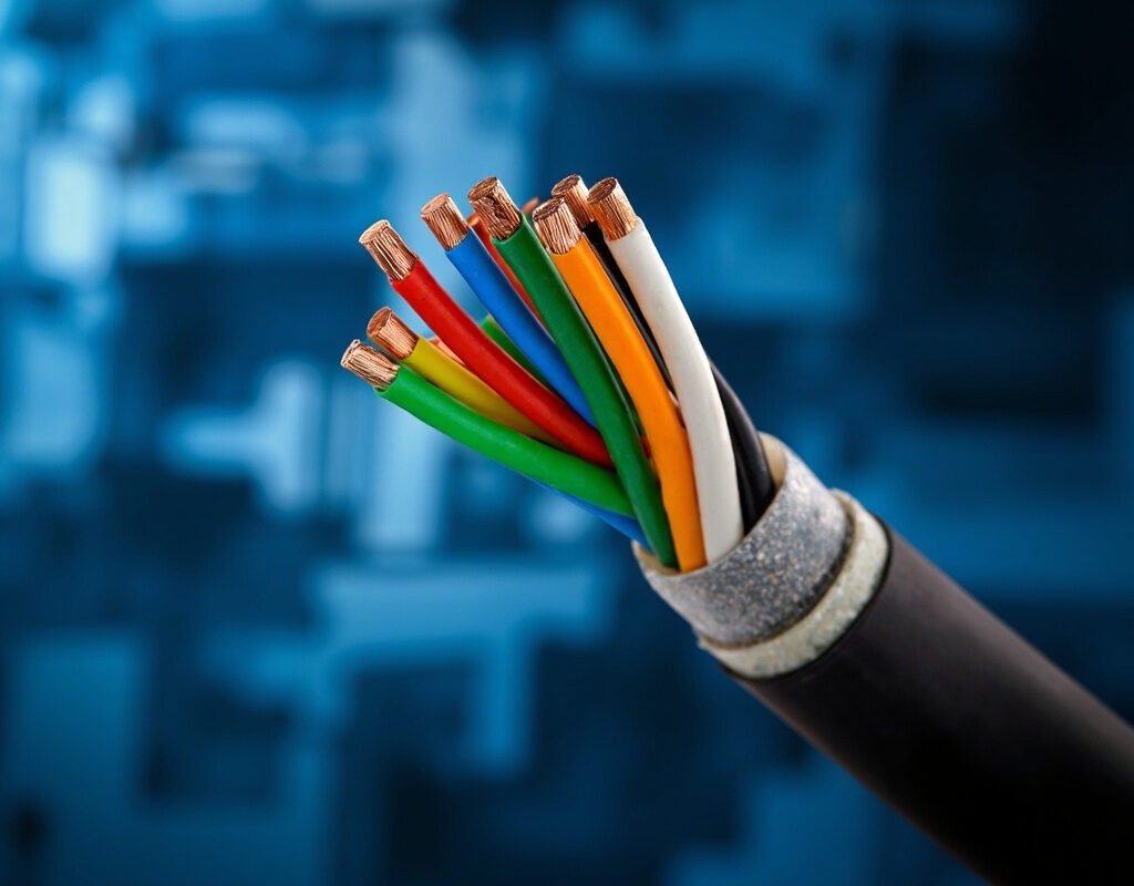
As automated machines grow more complex, so do their cabling requirements. A modern CNC machining center may need 30+ individual cables for power, control, feedback, pneumatics, and data—each requiring routing, strain relief, connectorization, and documentation. Multi-core high flex cable products offer a powerful solution: consolidating multiple circuits into a single jacket reduces installation complexity, improves reliability, and optimizes space utilization in crowded cable carriers and dress packs.
However, multi-conductor high flex cable design is not simply about stuffing more wires into a tube. Conductor sizing, pair assignment, shielding strategy, and thermal management must all be carefully engineered to ensure the consolidated cable performs as well—or better—than separate runs.
This guide covers the complete high flex multi core cable design methodology for complex automation systems.
When Multi-Core Makes Sense vs. When It Doesn’t
Advantages of Consolidation
| Benefit | Quantified Impact |
|---|---|
| Cable management improvement | 50–80% reduction in cable ties, conduits, and supports required |
| Space optimization | 30–50% smaller cross-section in energy chains (vs. equivalent separate cables) |
| Reduced connection points | Fewer entry points into enclosures = lower risk of ingress contamination |
| Improved appearance | Cleaner machine aesthetic; easier maintenance navigation |
| Lower total material cost | Often 15–30% less expensive than equivalent individual cables |
Disadvantages and Risks
| Concern | Mitigation Strategy |
|---|---|
| Larger diameter = stiffer (harder to route tightly) | Select highly flexible PUR/TPE jackets; use Class 6/7 stranding |
| Cross-talk between adjacent conductors | Proper pair/shield configuration; maintain adequate insulation thickness |
| Custom lead time (non-standard configurations) | Plan ahead; work with supplier who stocks configurable options |
| More complex replacement (if partial failure) | Design modular segments; document conductor map thoroughly |
Decision Framework
Use multi pair high flex cable when:
- 3+ circuits share the same routing path
- Space in cable carrier/dress pack is limited
- Circuits are functionally related (e.g., all motor power+brake+encoder for one axis)
- Installation labor cost exceeds cable material cost differential
- Replacement can be scheduled during planned downtime
Keep circuits separate when:
- Functions require different environmental ratings (e.g., high-temp spindle vs. ambient I/O)
- Different flex life requirements (heavy-duty power vs. light-duty signal)
- Regulatory separation required (safety circuits must be physically separated)
- Individual circuits may need independent replacement
Hybrid Cable Architecture Design
Power + Control Combinations
The most common multi-conductor flex cable configuration combines motor power with associated control/feedback:
Standard Servo Axis Hybrid (6-conductor example):
| Position | Function | Gauge | Insulation Color | Notes |
|---|---|---|---|---|
| 2 | Phase V (power) | 2.5 mm² | Blue | |
| 3 | Phase W (power) | 2.5 mm² | Black | |
| 4 | PE (ground) | 2.5 mm² | Green/Yellow | Symmetrical placement preferred |
| 5 | Brake (+) | 0.75 mm² | Red | Holding brake supply |
| 6 | Brake (-/monitor) | 0.75 mm² | White | Return + optional monitor contact |
Enhanced version (with encoder integrated — 14+ conductors):
Add 4 twisted pairs (differential A//A, B//B, Z//Z, power) plus shield, bringing total to approximately 16–18 conductors in a single hybrid control power cable.
Electrical + Pneumatic Hybrids
Some advanced multi-core high flex cable products integrate pneumatic or hydraulic lines alongside electrical conductors:
| Configuration | Applications | Key Considerations |
|---|---|---|
| Electrical + coolant hose | Spindle cooling, mold temperature control | Fluid compatibility; leak detection provisions |
| Electrical + fiber optic | Vision systems, long-distance data | Fiber bend radius much tighter than electrical |
Warning: Mixing fluids and electricity in one cable requires careful design to prevent fluid ingress to electrical components in case of hose rupture. Look for products with compartmentalized construction (separate chambers for each medium).
Conductor Pairing and Assignment Strategy
Pairing Principles
How you group conductors within a high flex multi core cable directly impacts EMI performance and signal integrity:
Rule 1: Pair complementary signals together
- Send and return for same circuit (e.g., +24V and 0V for a solenoid)
- Differential pair halves (A and /A; B and /B)
- Twisted together for noise rejection
Rule 2: Separate incompatible circuits
- Never put power conductors in the same pair as sensitive analog signals
- Maintain physical separation within the cable cross-section (use filler elements)
Rule 3: Group by voltage class
- All high-voltage conductors together
- All 24V DC control together
- All low-voltage analog together
- Place shields between groups when possible
Ideal Cross-Section Layout
For a representative multi-conductor flexible cable combining power, control, and data:
Cross-sectional view (example layout):

     ┌─────────────────────────────┐
     │  Overall Shield (braid)      │
     │  ┌───────────────────────┐  │
     │  │  Filler (center)       │  │
     │  │ ┌───┐┌───┐┌───┐┌───┐  │  │
     │  │ │U/V││W/PE││B+ ││B- │  │  │  ← Power conductors (outer ring)
     │  │ └───┘└───┘└───┘└───┘  │  │
     │  │ ┌───┐┌───┐┌───┐┌───┐  │  │
     │  │ │Enc││Enc││Lim││Lim│  │  │  ← Encoder pairs (middle ring, twisted)
     │  │ └───┘└───┘└───┘└───┘  │  │
     │  │ ┌───┐┌───┐           │  │
     │  │ │IO1││IO2│ ...       │  │  ← Control I/O (inner positions)
     │  │ └───┘└───┘           │  │
     │  └───────────────────────┘  │
     │  Outer Jacket (PUR)          │
     └─────────────────────────────┘
Key principles illustrated:
- Power conductors placed outermost — they carry highest current and generate most heat; placing them near jacket improves cooling
- Twisted pairs centrally located — maximum protection from external EMI
- Filler maintains round profile — prevents deformation during bending
- Overall shield surrounds everything — provides final EMI barrier
Thermal Management in Dense Multi-Core Cables
Derating Factors for Bundled Conductors
When multiple current-carrying conductors are bundled in a multi-core high flex cable, mutual heating reduces each conductor’s current-carrying capacity:
IEC 60364-5-52 Group Derating Factors (approximate):
| Number of Current-Carrying Conductors | Derating Factor |
|---|---|
| 7–9 | 0.70 |
| 10–12 | 0.65 |
| 13–15 | 0.60 |
| 16–19 | 0.57 |
| 20–24+ | 0.54 |
Practical example:
You need 3× power conductors rated for 20A each in standard conditions.
In a multi-conductor high flex cable with 18 active conductors total:
- Effective capacity per conductor = 20A × 0.57 = 11.4A
- To achieve 20A actual capacity: select conductor sized for 20/0.57 = 35.1A → use next standard size (~35–40A rating)
Conclusion: Dense multi-core cables often require larger gauge than expected due to thermal derating. Always apply group correction factors before finalizing specifications.
Standards and Testing
| Standard | Relevance | Key Requirement |
|---|---|---|
| IEC 60227-7 (Flexible cables) | International | Flex test (30,000 cycles min for flex-rated) |
| EN 50525 (Harmonized flexible cables) | European CE marking | Harmonized designation system |
| VDE 0298 (Flexible cable application guide) | German/European | Detailed guidance for selection and use |
| NFPA 79 (Industrial Machinery) | US NEC Article | Wiring methods for machine tool cables |
Conclusion
Multi-core high flex cable represents a mature engineering discipline that, when properly applied, delivers significant advantages in installation efficiency, space optimization, and system reliability. Success depends on thoughtful conductor assignment (pairing compatible signals together while separating incompatible ones), appropriate derating for thermal effects in dense bundles, and selecting the right balance between consolidation benefits and functional independence requirements. For complex automation systems, working with experienced hybrid cable manufacturers who understand these nuances ensures optimal results.
Multi-core cable expertise from Iflexcable.