
Robot Dress Package Cable
Introduction: The Nervous System of the Robotic Arm A modern 6-axis industrial robot without its robot dress package cable is a motionless sculpture of cast iron and servomotors. The dress pack—the integrated…
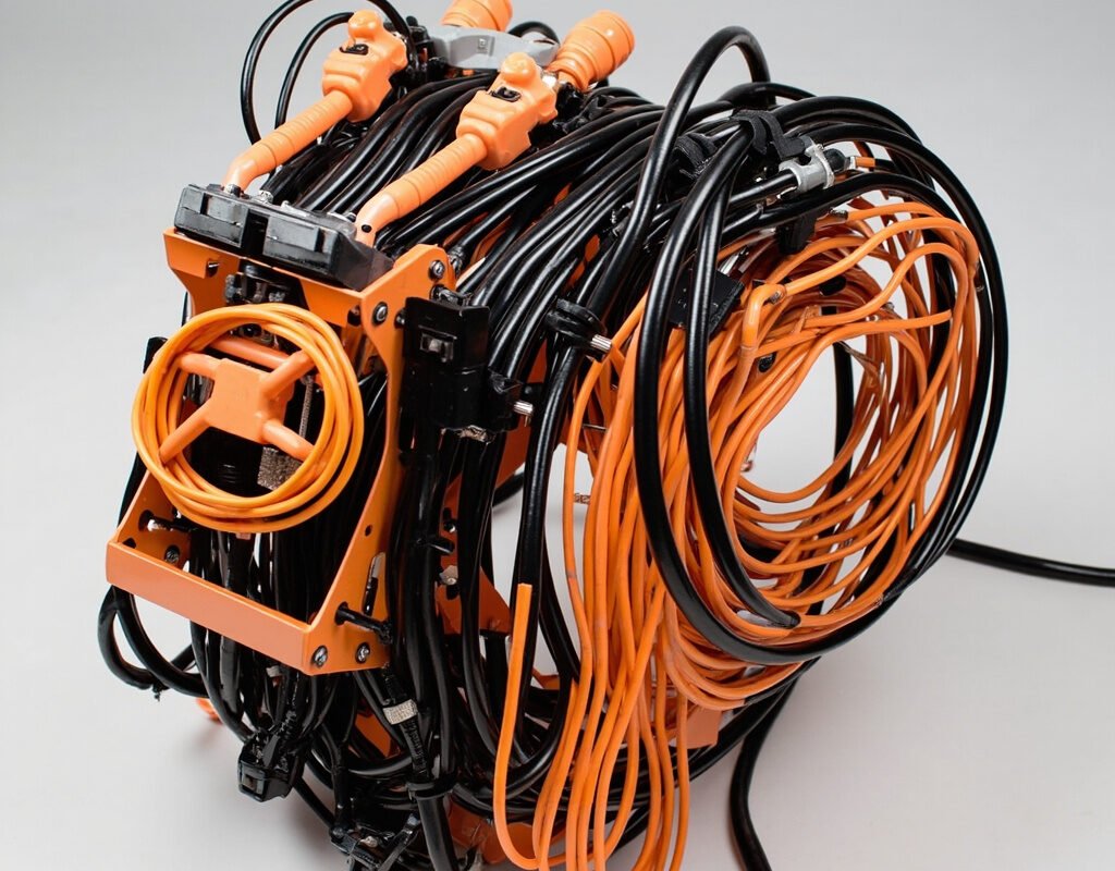
Introduction: The Nervous System of the Robotic Arm
A modern 6-axis industrial robot without its robot dress package cable is a motionless sculpture of cast iron and servomotors. The dress pack—the integrated bundle of power, signal, data, pneumatic, and fluid lines that follows every articulation of the robot’s wrist—is arguably the most critical yet most overlooked subsystem in robotic automation.
Robot dress package cable failures account for an estimated 40–60% of all unscheduled robot downtime across global manufacturing facilities. When a dress pack fails mid-cycle, production stops. When it fails catastrophically (cable breakage inside joints), repair costs escalate dramatically due to disassembly requirements.
This engineering guide covers dress pack cable design principles, material selection, installation best practices, and lifecycle management strategies that minimize downtime and maximize return on investment.
Anatomy of a Robot Dress Pack
Core Components
| Component | Function | Typical Specification |
|---|---|---|
| Encoder feedback cables | Position/velocity feedback | Twisted pair or quadruple, shielded, low capacitance |
| Brake release cables | Servo brake de-energization control | 2–4 core, 300V, flexible |
| Data/fieldbus cables | Communication to controller | DeviceNet, Profinet, EtherCAT, CC-Link |
| I/O sensor cables | End-effector sensor signals | Multi-core, unshielded or individually shielded |
| Pneumatic lines | Gripper actuation, vacuum generation | PU tubing, Ø4-Ø10mm, push-to-connect fittings |
| Fluid lines (optional) | Coolant delivery, lubrication | Specialized hose for specific media |
Physical Architecture
Typical Dress Pack Layout (outside-in):

Controller Interface
    │
    ├─ Base mounting bracket / strain relief
    │   └─ Cable bundle entry point (fixed)
    │
    ├─ Axis 1-3 (major axes): Large-radius sweep
    │   └─ Cables experience BENDING (not torsion)
    │       Bend radius: 8-12× OD typically
    │
    ├─ Axis 4-5 (wrist axes): Transition zone
    │   └─ Cables transition from bending to TORSION
    │       Critical zone for cable stress
    │
    └─ Axis 6 (flange): Maximum torsion zone
        └─ End-effector connection
            Torsion angles: ±180° to ±360° per cycle
            THIS is where most failures originate
Mechanical Stress Analysis
The Two Stress Regimes
Understanding the fundamental difference between bending stress and torsional stress is essential for proper robot cable harness specification:
Bending Stress (Axes 1-3):
σ_bending = (E × y) / R

Where:
  E = Young's modulus of conductor/jacket material
  y = distance from neutral axis (half the cable OD)
  R = bend radius

Design rule: Keep σ_bending below fatigue limit by ensuring
R ≥ 8×OD for continuous flexing applications
Torsional Stress (Axes 4-6):
τ_torsion = (T × r) / J

Where:
  T = applied torque (from wrist rotation)
  r = radius from cable center
  J = polar moment of inertia of cable cross-section

Critical insight: Torsional stress concentrates at the OUTER layers
of multi-core cables — the outermost conductors experience the highest
stress and fail FIRST in torsion-dominated dress packs.
Why Standard Cables Fail in Dress Packs
| Failure Mode | Root Cause | Typical Time to Failure | Prevention Strategy |
|---|---|---|---|
| Corkscrewing (helical deformation) | Torsion exceeds cable’s natural twist tolerance | 1–5 million cycles | Specify torsion-rated cable; use counter-twist bundling |
| Shield failure (foil separation) | Foil shield cannot accommodate twist | 0.1–1 million cycles | Use braided shield (>85% coverage); avoid foil-only shields in torsion zones |
| Jacket cracking at stress points | Repeated compression/tension cycles concentrate damage | 1–10 million cycles | Use TPU/PUR jacket; add protective sleeves at high-stress points |
| Connector pin fatigue | Repeated flexing at cable-entry point | 0.5–2 million cycles | Use molded strain relief; overmolded backshells; right-angle connectors |
Material Selection for Dress Pack Components
Cable Jacket Materials
| Material | Flex Life (cycles) | Torsion Resistance | Abrasion Resistance | Temperature Range | Best Application |
|---|---|---|---|---|---|
| Flexible PVC | 1–2M | Fair-Poor | Good | -15°C to +80°C | Light-duty articulated arms |
| TPU/PUR | 5–15M | Good | Excellent | -40°C to +80°C | General-purpose industrial robots |
| Torsion-grade PUR | 10–30M | Very Good | Very Good | -40°C to +80°C | High-speed/high-acceleration robots |
| High-performance TPE | 15–40M | Excellent | Good | -50°C to +105°C | Premium dress pack specifications |
Conductor Specifications
For robotic dress package applications, never accept standard solid or lightly-stranded conductors:
| Stranding Class | Wires per mm² | Min Bends to Failure | Typical Use in Dress Packs |
|---|---|---|---|
| Class 2 (stranded) | 7–19 | 50,000–200,000 | Fixed wiring only |
| Class 5 (flexible) | 25–50 | 500K–2M | Low-motion dress pack sections |
| Class 6 (highly flexible) | 50–100+ | 2M–10M | Standard dress pack cable |
| Class 7 (extra flexible) | 100–200+ | 10M–30M+ | High-performance dress pack; torsion zones |
Design Principles for Reliable Dress Packs
Principle 1: Decouple Where Possible
Not every cable needs to travel the full length of the robot:
Optimal strategy: "Distributed intelligence"

Instead of running ALL cables from base to end-effector:
├── Place I/O modules at Axis 3 (elbow) → shorter sensor cable runs
├── Use distributed valve islands → pneumatic lines stop at elbow
├── Mount small servo drives near motors → shorter power cable runs
│
Result: Each cable segment experiences LESS total movement
→ Extended service life proportional to reduced travel distance
Principle 2: Counter-Rotation Bundling
When cables must traverse torsion zones (Axes 4-6), arrange them with intentional pre-twist:
Counter-rotation technique:

Before securing the dress pack:
1. Lay all cables straight and parallel
2. Apply a PRE-TWIST equal to ~50% of the expected rotation angle
   in the OPPOSITE direction of the dominant rotation direction
3. Secure bundles with hook-and-loop ties (NOT plastic zip ties)
4. Allow the pre-twist to absorb the operational torsion

Result: Net torsion on each individual cable is REDUCED by 50%
→ Effective flex life approximately DOUBLED
Principle 3: Independent Suspension
Never bind cables into an overly rigid bundle:
Correct approach: "Loose bundle" method
├── Each cable has slight independent slack within the bundle
├── Hook-and-loop ties at 150–200mm intervals (allows micro-movement)
├── Cables can shift relative to each other under torsion
│
Incorrect approach: "Rigid bundle" method
├── All cables tightly bound together with zip ties every 50mm
├── Bundle behaves as one rigid body → outer cables overstretched
├── Inner cables buckle → premature failure of both inner AND outer cables
Principle 4: Stress Point Protection
Identify and protect critical stress concentration points:
| Location | Stress Type | Protection Method |
|---|---|---|
| Axis 3 (elbow) outer radius | Maximum bending stress | Abrasion sleeve; larger bend radius support |
| Axis 4-5 internal routing | Bending-to-torsion transition | Anti-torsion sleeve; smooth bore conduit |
| Axis 6 (flange) interface | Maximum torsion + connector stress | Torsion-lock connector; molded boot; secondary retention |
| End-effector junction | Multi-axis compound motion | Articulated protection; quick-disconnect interface |
Connector Systems for Dress Packs
Connector Requirements
| Requirement | Specification | Rationale |
|---|---|---|
| Vibration resistance | IEC 60068-2-6 compliant | Robot vibration spectrum: 5–500Hz, up to 2g |
| Retention force | ≥50N axial pull-off | Prevents accidental disconnect during operation |
| IP rating | IP65 minimum; IP67 preferred | Coolant spray, dust, metal chips |
| Strain relief | Integral or add-on overmold | Prevents cable/conductor fatigue at entry point |
| Coding/keying | Mechanical or color coding | Prevents misconnection during reassembly |
Recommended Connector Families
| Connector Type | Pin Count Range | Suitability for Dress Packs | Notes |
|---|---|---|---|
| M12 A-coded/D-coded | 3–12 pins | Good for power/signal | Industry-standard; widely available |
| M8 | 3–6 pins | Compact I/O | Space-constrained end-effectors |
| Han modular | Modular inserts | High-pin-count applications | Heavy-duty; excellent for base connections |
| Push-pull (LEMO/Fischer) | 2–32 pins | Premium applications | Highest reliability; higher cost |
| Industrial RJ45 | 8-pin Ethernet | Data only | Requires protective housing in harsh environments |
Maintenance and Lifecycle Management
Preventive Inspection Schedule
| Interval | Inspection Items | Action Triggers |
|---|---|---|
| Weekly | Connector security; jacket surface condition | Plan replacement if cracks/chafing visible |
| Monthly | Full dress pack photo documentation; bend radius verification | Compare to baseline; note progressive degradation |
| Quarterly | Continuity test all circuits; insulation resistance measurement | Any circuit >100MΩ drop from baseline |
| Annually | Partial disassembly inspection of internal routing; torque check on all fasteners | Full dress pack replacement if >20% life consumed |
Predictive Replacement Criteria
Replace the entire robot dress package cable assembly when:
- Cycle count approaches rating: If robot performs 20 cycles/min × 16 hrs/day × 250 days = 4.8 million cycles/year, and cable rated for 10M cycles, plan replacement at ~2 years regardless of appearance.
- Visible jacket degradation: Cracking, gloss loss, or permanent deformation (ovalization) indicates polymer fatigue even if no electrical fault exists.
- Connector contact wear: Insertion force decreasing noticeably (indicating contact spring relaxation).
- Application change: New end-effector or motion program significantly changes stress profile—existing dress pack may be underspecified.
Conclusion
The robot dress package cable is not an afterthought accessory—it is a precision-engineered subsystem whose reliability directly determines overall equipment effectiveness. By applying the mechanical stress analysis, material selection criteria, design principles, and lifecycle management practices outlined in this guide, engineers specify and maintain dress packages that deliver maximum uptime and minimum total cost of ownership across the full robotic system lifecycle.
Dress pack engineering expertise from Iflexcable.