
Clean Room Cable
Introduction: When a Single Particle Ruins a Wafer In a semiconductor fabrication clean room operating at ISO Class 3, a single 0.3-micron particle settling onto a wafer during photolithography can destroy dozens…
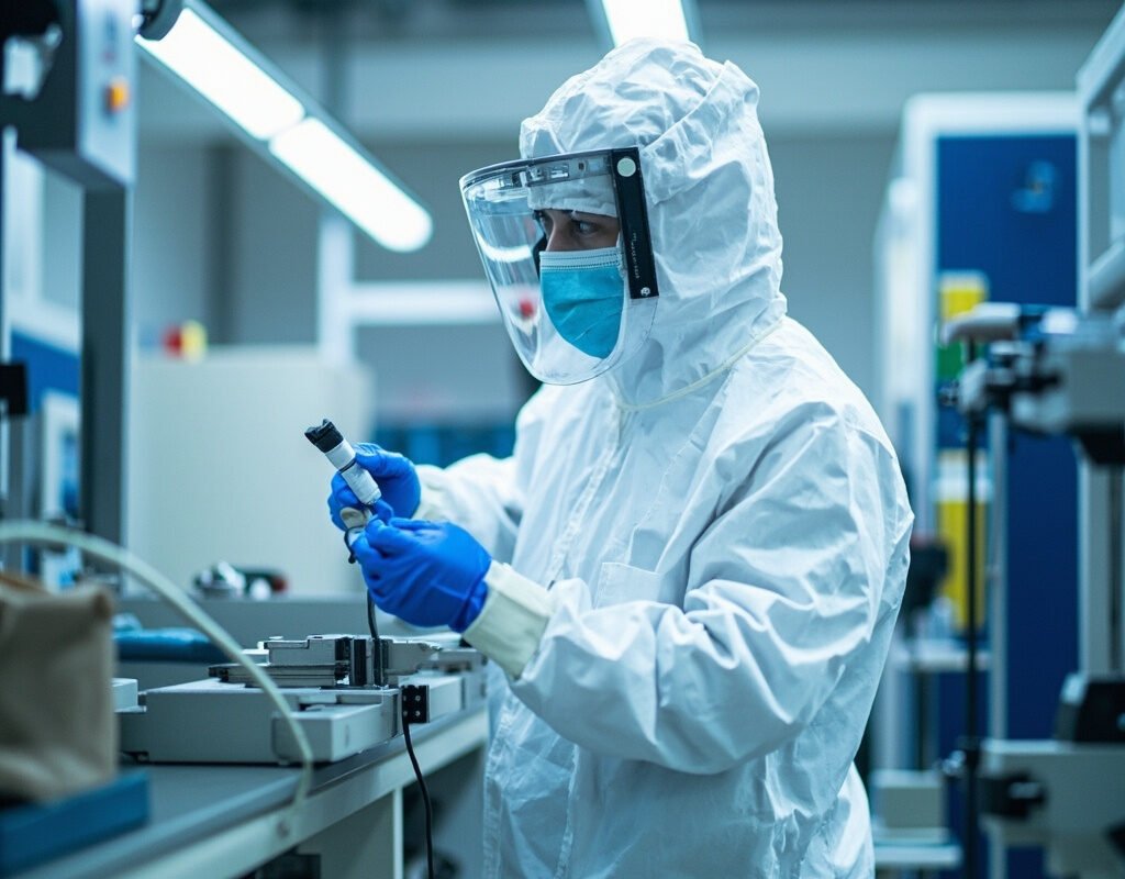
Introduction: When a Single Particle Ruins a Wafer
In a semiconductor fabrication clean room operating at ISO Class 3, a single 0.3-micron particle settling onto a wafer during photolithography can destroy dozens of transistors, potentially killing an entire $50,000 wafer. In pharmaceutical manufacturing, particulate contamination of sterile injectable formulations poses patient safety risks and regulatory consequences.
Yet every component installed in these spaces—including clean room cable—is a potential particle generator. Cable jackets degrade through friction. Outgassed volatiles condense on optics. Plasticizers migrate to surfaces. Every material choice matters when the acceptable particle count is measured in single digits per cubic meter.
This guide explains how cleanroom compatible cable products are engineered, tested, and specified for the most particle-sensitive environments on Earth.
Understanding Clean Room Classification
ISO 14644-1 Classification System
| ISO Class | Max Particles ≥0.1µm/m³ | Max Particles ≥0.5µm/m³ | Typical Environment |
|---|---|---|---|
| ISO Class 3 | 1,000 | 35 | Semiconductor critical path; reticle handling |
| ISO Class 5 | 100,000 | 292 | Semiconductor fab general; pharmaceutical aseptic fill |
| ISO Class 7 | 35,200,000 | 352,000 | Pharmaceutical manufacturing; medical device clean room |
| ISO Class 9 | Not typically controlled | 35,200,000 | Controlled environment (non-critical) |
Practical context: An ISO Class 5 room permits only 292 particles of 0.5µm or larger per cubic meter of air. By comparison, ordinary indoor air contains millions of particles at this size. A clean room cable installed in this space must not contribute measurably to this already minuscule budget.
Federal Standard 209E (Legacy Reference)
While superseded by ISO 14644, FS 209E terminology remains in widespread use:
| FS 209E Equivalent | ISO 14644-1 Class | Common Name |
|---|---|---|
| Class 10 | ISO 4 | “Class 10 clean room” |
| Class 100 | ISO 5 | “Class 100 clean room” |
| Class 1,000 | ISO 6 | “Class 1,000” |
| Class 10,000 | ISO 7 | Most common spec for industrial clean rooms |
| Class 100,000 | ISO 8 | Less critical clean room |
Particle Generation Mechanisms in Cables
Mechanism 1: Mechanical Particle Release
As cleanroom cable moves (in drag chains, robot dress packs, or during installation), friction between the jacket surface and surrounding surfaces generates particles:
Particle generation rate ∝ (contact pressure × sliding velocity × surface roughness)

Key factors:
├── Jacket material hardness (softer materials generate fewer particles)
├── Surface finish (smooth, glossy surfaces reduce particle generation)
├── Presence of fillers/additives (some additives create dust)
│
Lowest particle generation materials (ranked):
1. Smooth PUR (thermoplastic polyurethane) – best overall
2. FEP (fluorinated ethylene propylene) – excellent but stiff
3. Silicone rubber – very good; slightly sticky surface traps particles
4. PTFE – excellent chemical properties; moderate particle generation
5. PVC – POOR; plasticizers migrate; avoid in Class 5+
Mechanism 2: Outgassing and VOC Condensation
Even if a low outgassing cable generates zero solid particles, volatile compounds evaporating from its materials can condense on sensitive surfaces:
Outgassing sources in cable construction:
| Source | Volatile Compounds | Impact |
|---|---|---|
| Curing residues | Solvents, uncured monomers | Short-term outgassing spike after manufacture |
| Antioxidant decomposition | Phenolic fragments | Long-term low-level emission |
| Flame retardant breakdown | Halogenated compounds (if present) | Highly problematic; corrosive deposits |
| Adhesive residues (from tapes/markings) | Various organics | Often overlooked contamination source |
NASA outgassing standard (SP-R-0022A) sets industry benchmarks:
| Parameter | Test Method | Acceptance Limit |
|---|---|---|
| Collected Volatile Condensable Materials (CVCM) | ASTM E595; same conditions | ≤0.1% |
These limits are mandatory for spacecraft-grade low outgassing cable and are increasingly adopted as best-practice specifications for semiconductor and optical equipment cabling.
Mechanism 3: Electrostatic Attraction
Particles that exist in the clean room atmosphere are attracted to charged clean room cable surfaces:
Electrostatic attraction force: F_e = q × E

Where q = particle charge, E = electric field strength

Mitigation strategies:
├── Static-dissipative jacket materials (surface resistivity 10⁶–10⁹ Ω/sq)
├── Proper grounding of cable shields
├── Maintaining humidity 45–55% RH (reduces static charge accumulation)
└── Ionized air systems in critical areas
Clean Room Cable Testing and Certification
Particle Emission Testing (IEC 61340-4-1)
The definitive test method for particle free cable qualification:
Test protocol summary:
1. Cable specimen (minimum 1 meter) mounted on test apparatus
2. Pre-cleaned in laminar flow hood to remove existing particles
3. Subjected to defined flexing/bending cycle (typical: 10,000 cycles)
4. Particle counting (laser particle counter) during and after flexing
5. Results reported as: particles generated per meter per 1000 cycles

Acceptance criteria (example specification):
├── ISO Class 5 compatible: ≤100 particles (≥0.3µm)/m/1000 cycles
├── ISO Class 7 compatible: ≤1,000 particles (≥0.3µm)/m/1000 cycles
└── ISO Class 8 compatible: ≤10,000 particles (≥0.3µm)/m/1000 cycles
Outgassing Qualification Testing
For semiconductor manufacturing cable requiring outgassing certification:
| Test | Standard | Duration | Conditions | Pass Criterion |
|---|---|---|---|---|
| Accelerated aging | IEC 60216 | 1,000–10,000 hours | Elevated temperature | Property retention ≥50% |
| Surface analysis | XPS/AES spectroscopy | N/A | Vacuum chamber exposure | No detectable silicones on witness sample |
Material Selection Matrix for Clean Rooms
Jacket Material Comparison
| Material | Particle Generation | Outgassing Level | Chemical Resistance | Flexibility | Cost | Best Clean Room Class |
|---|---|---|---|---|---|---|
| FEP | Low | Extremely Low | Outstanding | Fair (stiff) | High | ISO 1–5 |
| PTFE | Low-Moderate | Very Low | Outstanding | Fair | Very High | ISO 3–5 |
| Silicone rubber | Low | Low | Good | Very Good | Moderate-High | ISO 5–7 |
| TPE-S (special grade) | Low | Low | Good | Very Good | Moderate | ISO 5–7 |
| PVC (standard) | HIGH | HIGH | Fair | Good | Low | ISO 8+ only |
| Halogen-free PE | Low | Very Low | Moderate | Good | Low-Moderate | ISO 5–7 |
Conductor and Insulation Considerations
Beyond jacket material, cleanroom compatible cable requires attention to:
| Component | Concern | Recommended Approach |
|---|---|---|
| Insulation | Outgassing from polymer | FEP, PTFE, or specially formulated polyolefin insulation |
| Shield materials | Metallic particle shedding | Bonded foil-shield (prevents loose foil pieces) or served braid |
| Fillers/separator tape | Fibrous particle generation | Non-woven polyester (trapped fibers) or no filler (compact construction) |
| Identification markings | Ink outgassing/laser marking debris | Laser-marked identification (no ink); or molded-in color stripes |
| Connector hardware | Metallic particle generation from mating | Stainless steel contacts; minimal insertion/removal debris |
Application-Specific Guidelines
Semiconductor Manufacturing
The most demanding clean room cable application domain:
| Process Area | ISO Class | Cable Requirements | Special Considerations |
|---|---|---|---|
| Etch/Deposition | ISO 5–7 | Chemical resistance + low particle | Must resist process gases (HF, Cl₂ plasmas) |
| Wafer probing/test | ISO 5–7 | Signal integrity + cleanliness | Shielding effectiveness critical |
| Equipment interconnect | ISO 7 | General clean room compliance | Cost-effective solutions acceptable |
| Sub-fab (utility) | ISO 8 | Basic cleanliness | Standard industrial cable often adequate |
Pharmaceutical and Medical Device Manufacturing
| Application Area | Regulatory Framework | Key Cable Requirements |
|---|---|---|
| Sterile product packaging | Same as above | Washdown-compatible; detergent-resistant jacket |
| Medical device clean room | FDA QSR; ISO 13485 | Biocompatibility (ISO 10993) if patient-contact possible |
| Laboratory automation | GLP/GMP guidelines | Chemical resistance to lab solvents; easy decontamination |
Installation Best Practices
Pre-Installation Preparation
- Receive cables in original packaging directly into clean room anteroom (gray room). Do not open in general factory area.
- Wipe down cable exterior with clean room-approved wipe and IPA solution before introducing into classified space.
- Condition cables in the clean room environment for minimum 24 hours before installation (prevents thermal outgassing burst from temperature equilibration).
- Cut using clean-room approved tools with particle extraction (thermal cutters preferred over mechanical shears).
During Installation
| Practice | Rationale |
|---|---|
| Support cable continuously during routing | Dragging across floors/walls generates particles |
| Use clean room-compatible cable ties (hook-and-loop or specialized clean room ties) | Standard zip ties generate particles when trimmed |
| Minimize rework/repositioning | Each handling event adds particle load |
| Document exact routing for future reference | Enables efficient maintenance without exploratory handling |
Conclusion
Specifying clean room cable requires understanding not just electrical and mechanical requirements, but also the invisible parameters of particle generation, outgassing behavior, and electrostatic characteristics that determine whether a cable enhances or undermines the integrity of the controlled environment. By applying the classification framework, testing protocols, material selection matrix, and installation guidelines in this guide, engineers ensure their cabling infrastructure supports rather than compromises the stringent cleanliness requirements of semiconductor, pharmaceutical, and medical device manufacturing operations.
Clean room cable technology from Iflexcable.