
Reeling Cable for Drum and Winch Systems — Engineering Design Manual
Fundamental Mechanics of Reeling Cable Operation The Reeling Process — Step by Step Step Understanding the mechanical cycle is essential for proper cable selection: PhaseCable StateDominant StressesUnwindingCable peels off drum under tensionReverse…
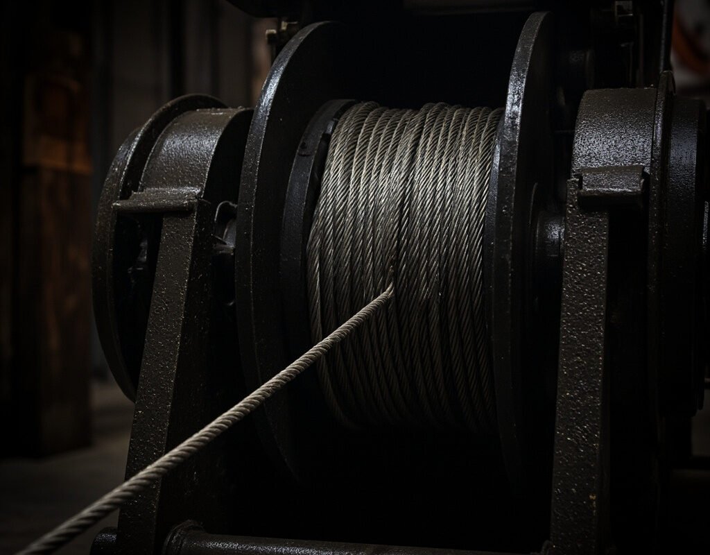
Fundamental Mechanics of Reeling Cable Operation
The Reeling Process — Step by Step Step
Understanding the mechanical cycle is essential for proper cable selection:
| Phase | Cable State | Dominant Stresses |
|---|---|---|
| Unwinding | Cable peels off drum under tension | Reverse bending + axial tension + slight untwist |
| Free span | Cable hangs in catenary between drum and moving equipment | Gravity sag + tension + minimal bending |
| Rewinding | Cable winds onto drum under controlled tension | Forward bending + axial compression between layers + helical twist |
Spiral Bending — The Core Engineering Challenge
As cable winds onto a drum, it experiences spiral (helical) bending rather than simple planar bending. The effective bend radius changes continuously:
$$R_{eff}(x) = R_{drum} + (n – 0.5) \cdot d_c$$
Where:
- R_eff(x) = effective bend radius at position x on the drum
- R_drum = drum barrel radius
- n = current layer number (starting from 1)
- d_c = cable outer diameter
Critical Insight: On a typical 400mm diameter drum with 18mm cable:
- Layer 1 effective BR: (200 + 0.5 × 18) = 209mm (= 11.6 × OD ✓ acceptable)
- Layer 5 effective BR: (200 + 4.5 × 18) = 281mm (= 15.6 × OD ✓ excellent)
- But the transition zone (where cable leaves the drum) experiences the tightest bend — always equal to R_drum + 0.5 d_c
Design Rule of Thumb:
$$D_{drum} \geq 20 \times d_c \quad (\text{minimum})$$
$$D_{drum} \geq 25 \times d_c \quad (\text{recommended for long life})$$
Anti-Torque (Zero-Twist) Construction — Essential Technology
One of the most destructive forces in reeling applications is cable twist accumulation. When a non-optimized cable reels repeatedly, it develops a permanent cast or spiral tendency that causes:
- Tangling and bird-caging during payout
- Difficulty laying neatly on the drum
- Internal conductor stress from accumulated torsional strain
- Connector rotation and loosening
Anti-torque construction methods:
| Method | Principle | Effectiveness | Cost Impact |
|---|---|---|---|
| Inner cordage element | Central non-metallic cord absorbs torque | ★★★★ | +10% |
| Balanced stranding | Calculate lay angles so vector sum of torques ≈ 0 | ★★★★★ | +20% |
| Short-pitch stranded conductors | Reduces individual conductor torsional stiffness | ★★★ | +8% |
| Kevlar torque-balancing layer | Aramid fibers oriented to counteract twist | ★★★★ | +25% |
Mathematical basis for balanced lay design:
$$\sum_{i=1}^{n} T_i \cdot \cos(\alpha_i) \approx 0$$
Where T_i is the torque contribution of layer i, and α_i is the lay angle. Advanced manufacturers use finite-element modeling to optimize lay geometries for specific drum sizes and reeling speeds.
Reeling Cable Construction Details
Conductor System
| Parameter | Standard Reeling | Heavy-Duty Reeling | Mining/Offshore Grade |
|---|---|---|---|
| Stranding | IEC 60228 Class 5 | Class 6 | Class 6 + rope-lay for large CSA |
| Max cross-section | 35 mm² | 70 mm² | 120 mm²+ (special) |
| Annealing | Soft | Fully soft | Extra-soft (elongation > 30%) |
Insulation System
Recommended hierarchy for reeling cable insulation:
- XLPE (Cross-linked Polyethylene) — Best overall choice. Excellent mechanical toughness, good dielectric strength, wide temperature range, resistant to oils encountered around winch gearboxes. Temperature rating: 90°C wet / 105°C dry.
- EPR (Ethylene Propylene Rubber) — Superior flexibility at low temperatures. Preferred for sub-zero applications. Slightly higher water absorption than XLPE but still acceptable. Temperature rating: 90°C.
- Silicone Rubber — For extreme temperature applications (-60°C to +200°C). Softer, more prone to physical damage, used only when temperature demands justify.
- PVC — Not generally recommended for reeling applications except very light-duty indoor uses. Poor cold flex, limited temperature range, degrades under repeated bending faster than thermosets.
Bedding and Inner Layers
The bedding layer between insulated cores and the outer jacket serves multiple critical functions:
| Function | Material | Thickness |
|---|---|---|
| Filler (to achieve round profile) | PP or PET fillers | As needed |
| Anti-torque element | PP cordage or aramid yarn | Integrated into bedding |
| Separator (if armored) | PVC or PE tape | 0.2 mm |
| Water-blocking (optional) | Swellable powder/tape | Applied under jacket |
Outer Sheath Options
| Sheath Type | Application | Key Properties |
|---|---|---|
| PUR (cold-flex) | Freezer/cold storage, arctic | Retains flexibility to -50°C, special PU formula |
| PUR (chlorine-resistant) | Water treatment, swimming pool, chemical plants | Resists oxidation from chlorine/ozone |
| CR (Chloroprene/Neoprene) | Marine/offshore, heavy-duty | Excellent weathering, flame retardant, moderate oil resistance |
| NBR/PVC blend | Fuel/oil contact applications | Superior petroleum resistance |
| LSZH (low smoke zero halogen) | Enclosed spaces, transit systems | Fire-safe, low toxicity smoke |
Reeling System Types and Their Cable Requirements
Motor-Driven Reels (Constant Tension)
Motor-driven reels use an electric or hydraulic motor to maintain consistent cable tension during payout and take-up. This is the most common configuration for large-scale applications like mining shovels and port cranes.
| Parameter | Typical Range |
|---|---|
| Reeling speed | 0.5–120 m/min |
| Tension control | 50–500 N (depending on cable weight and span) |
| Cable length capacity | 30–300 meters |
| Duty cycle | Continuous or intermittent |
Cable specification emphasis: Focus on abrasion resistance (constant drum contact) and tensile strength (controlled tension). Anti-torque construction is essential for neat layering at high speeds.
Spring-Driven Reels (Retractable)
Spring reels store energy in a clock-type or constant-force spring to automatically retract the cable. Common in tool balancers, light cranes, and workshop applications.
| Parameter | Typical Range |
|---|---|
| Cable length | 5–25 meters |
| Tension | 10–50 N |
| Applications | Tool holders, task lights, small hoists |
Cable specification emphasis: Small diameter and high flexibility take priority. Miniature reeling cables (OD 5–8mm) with extra-fine stranding are common.
Slip-Ring Equipped Reels
For applications requiring continuous rotation (like rotating platforms or turrets), the reel incorporates a slip ring assembly. Cable must pass through the hollow reel shaft.
Cable consideration: Must fit through the slip ring bore (often 12–25mm diameter limitation). May require custom miniaturized construction with reduced conductor count.
Comparison: Reeling Cable vs. Festoon Cable
| Criterion | Reeling Cable | Festoon Cable |
|---|---|---|
| Bend radius | Fixed by drum size (tight at drum, relaxed in free span) | Fixed by C-track geometry throughout |
| Twist behavior | Accumulates twist unless anti-torque designed | Minimal twist in well-designed systems |
| Space efficiency | Compact (drum mounted) | Requires full travel length of free space |
| Max travel distance | Limited by drum capacity (typically ≤ 300m) | Unlimited (C-track can be any length) |
| Speed capability | Higher speeds achievable | Limited by trolley dynamics |
| Installation complexity | Moderate (requires drum alignment) | Higher (full C-track assembly) |
| Maintenance | Periodic drum inspection, level-wind mechanism | Trolley wheel inspection, track cleaning |
| Cost | Drum adds significant capital cost | Track system cost scales with length |
| Best for | Long travels, space-constrained, high-speed | Short-medium travels, lower budget, simpler maintenance |
Decision Matrix:
- Choose Reeling if: Travel > 50m, space limited, high speed needed, clean aesthetic required
- Choose Festoon if: Travel < 50m, budget-sensitive, easy access for maintenance, variable routing needed
Drum Design Guidelines for Cable Engineers
Even though the drum is typically a mechanical engineering deliverable, cable engineers must understand and influence its design:
Critical Drum Parameters
| Parameter | Recommendation | Reason |
|---|---|---|
| Flange diameter | D + 2 × (layers × cable OD) + 20mm margin | Prevents cable jumping off |
| Surface finish | Smooth machined or polished (Ra < 3.2 µm) | Reduces abrasive wear on cable jacket |
| Material | Steel (powder-coated or stainless) or aluminum alloy | Rigidity prevents deflection under cable tension |
| Level-wind mechanism | Mandatory for multi-layer reeling | Prevents cable cutting into lower layers (the “cut-in” problem) |
| Drum speed ratio | Match cable linear speed to equipment speed | Mismatch causes slack or over-tension |
The Cut-In Problem and Its Prevention
When multi-layer reeling without a level-wind mechanism, upper-layer cables can be forced between lower-layer cables (“cutting in”), causing severe pinch damage:

Prevention strategies:
- Level-wind screw/nut mechanism: Most effective. Guides cable side-to-side synchronized with drum rotation
- Grooved drum barrel: Machined grooves accept each turn precisely. Limits number of layers but eliminates cut-in entirely
- Controlled tension: Proper tension keeps layers tight enough to prevent gaps where cut-in occurs
- Single-layer design: Accept reduced capacity for maximum reliability (common in critical applications)
Standards and Testing
| Standard | Scope | Key Test for Reeling Cable |
|---|---|---|
| VDE 0282 Part 2 | Flexible cables (German) | Specific reeling test procedure defined |
| UL 62 | Flexible cords and cables (US) | Crush and flex tests applicable |
| BS EN 50525 series | Flexible cables harmonized | Includes reeling-specific types |
| ASTM D2136 | Low-temperature bend | Important for outdoor reeling apps |
| ISO 19642-2 | Automotive (reference) | Flex-fatigue test methodology adaptable |
Manufacturer Test Data — What to Request
When evaluating reeling cable suppliers, request the following test reports:
- Flex life test (IEC 60227-7 modified for reeling): Report actual cycle count to failure
- Cold bend test (at minimum operating temperature): Confirm no cracking
- Abrasion test (kratz test per IEC 60811-404): Volume loss in mm³
- Torsion test: Degrees of twist sustained before conductor migration
- Tensile test (whole cable): Breaking strength in Newtons
- Aging test (thermal + UV): Property retention after accelerated aging
- Oil immersion test (IRVM 2303.1 or equivalent): Dimensional and property change after oil exposure
Troubleshooting Reeling Cable Problems
| Problem | Likely Cause | Diagnostic Steps | Solution |
|---|---|---|---|
| Uneven layering on drum | Level-wind malfunction, inconsistent tension | Watch reeling process; measure tension with dynamometer | Repair/adjust level-wind; calibrate tension controller |
| Jacket wear at drum contact | Excessive drum surface roughness, contamination | Inspect drum surface with finger; feel for rough spots | Polish drum, clean debris, consider drum liner |
| Conductor break at drum entry/exit | Tight bend radius + tension combination | Measure actual BR at entry point; compare to spec | Increase drum diameter or reduce cable OD |
| Connector rotation/loosening | Cable torque transmitted to termination | Mark cable and connector; observe rotation during operation | Install swivel fitting; upgrade to anti-torque cable |
| Water inside cable | Jacket breach (abrasion or cut), improper termination | Megohmmeter test; inspect for jacket damage | Locate and repair/replace damaged section |
Application Spotlights
Mining Excavator (Electric Rope Shovel)
| Requirement | Specification |
|---|---|
| Diameter | 45–65 mm (very large) |
| Voltage | 3–15 kV (medium voltage!) |
| Special features | Armor layer, extreme abrasion resistance, magnetic field immunity |
| Flex life target | > 2 million cycles (lower due to large size) |
| Unique challenge | Cable weighs 5–12 kg/m → massive tension forces |
Theater Stage Rigging
| Requirement | Specification |
|---|---|
| Diameter | 8–15 mm |
| Special features | Quiet operation (no squeaking against drum), aesthetically clean appearance, often includes DMX512 data lines alongside power |
| Noise limit | < 40 dB during reeling (critical for live performances) |
Automated Storage/Retrieval (AS/RS)
| Requirement | Specification |
|---|---|
| Duty cycle | Very high (24/7 operation possible) |
| Reliability requirement | MTBF > 50,000 hours |
| Special consideration | Often integrates encoder feedback and bus communication in same cable |
Conclusion
Reeling cable for drum and winch systems sits at the intersection of mechanical and electrical engineering, requiring deep understanding of spiral bending mechanics, torsional physics, and material science under cyclic loading. The key differentiators from other flexible cable categories — continuously varying bend radius, helical layer stacking, and tension-controlled deployment — demand specialized design approaches including anti-torque construction, optimized drum interface compatibility, and application-appropriate sheath material selection.
Engineers who master these principles can reliably specify reeling cable systems that provide decades of service in the world’s most demanding environments, from frozen mine pits to tropical port terminals to precision automation cells. The investment in quality reeling cable engineering pays returns in eliminated downtime, reduced maintenance burden, and enhanced operational safety.
Last updated: April 2026 | Standards: IEC 60227-7, VDE 0282 Part 2, UL 62, BS EN 50525