
Welding Cable Management for Robot Arms — Protect Your Investment
Understanding the Hostile Welding Cell Environment Environmental Hazard Matrix Hazard Source Effect on Cable/Hose Severity (1-5) Infrared/UV radiation Welding arc emits broad-spectrum EM radiation Polymer degradation (UV attack on organics), embrittlement ★★★★☆…
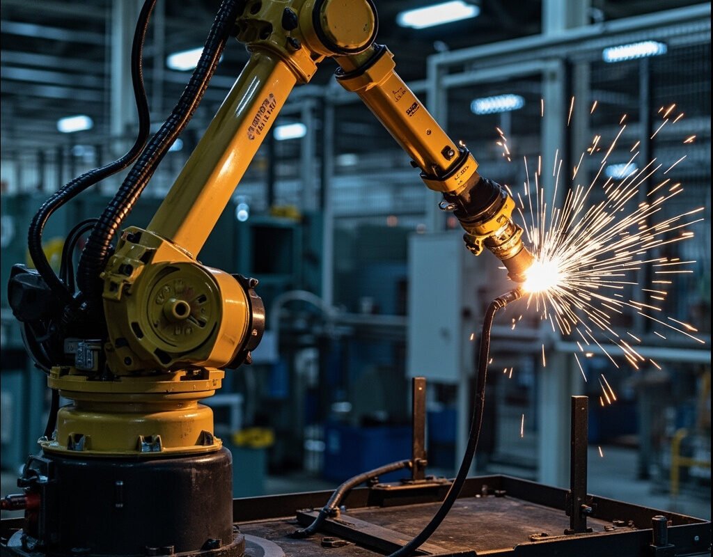
Understanding the Hostile Welding Cell Environment
Environmental Hazard Matrix
| Hazard | Source | Effect on Cable/Hose | Severity (1-5) |
|---|---|---|---|
| Infrared/UV radiation | Welding arc emits broad-spectrum EM radiation | Polymer degradation (UV attack on organics), embrittlement | ★★★★☆ |
| Heat soak | Cumulative heating from prolonged welding cycles | Accelerated aging, softening of thermoplastics above glass-transition temp | ★★★★☆ |
| EMI/RFI | Welding arc creates broadband electromagnetic noise up to MHz range | Signal corruption in encoders, sensors, communication buses | ★★★★☆ |
| Ozone generation | Arc produces ozone (O₃) which attacks rubber/elastomers | Cracking and premature aging of elastomeric materials | ★★★☆☆ |
| Mechanical abrasion | Repeated contact with workpiece fixtures, safety fencing | Physical wear, eventual cut-through | ★★★☆☆ |
| Coolant/water exposure | Leaks from cooling system, washdown | Water ingress, corrosion, tracking currents | ★★☆☆☆ |
| Oil/grease | Lubricants from robot joints, slide mechanisms | Swelling/degradation of certain polymers (especially PVC) | ★★☆☆☆ |
Weld Spatter Physics — The Primary Enemy
Weld spatter particles have characteristics that make them exceptionally destructive:
| Property | Typical Value | Implication |
|---|---|---|
| Ejection velocity | 1 – 15 m/s | Significant kinetic energy upon impact |
| Core temperature | 1400 – 2800°C (varies by process) | Instantly melts most polymers (melting point typically < 250°C) |
| Flight distance | Up to 1 meter from weld point | Entire dress package area is within danger zone |
| Rate of generation | 0.1 – 5 grams per minute (MIG) | Constant bombardment over production shift |
Material response to spatter contact:
| Material | Melting/Decomp. Point | Spatter Resistance |
|---|---|---|
| Standard PUR | 170–190°C | Poor-Moderate — resists briefly then fails |
| Silicone rubber | 250–300°C | Good — withstands brief contact, self-extinguishing |
| Glass fiber silicone | >500°C (glass protects) | Excellent — best practical choice |
| Viton/fluoroelastomer | 220–280°C | Good — expensive but chemical + heat resistant |
| PTFE (Teflon) | 327°C | Excellent — but poor mechanical durability |
| Metal conduit (stainless/aluminum) | N/A | Ultimate protection — but heavy and inflexible |
Dress Package Architecture — Component by Component
The Six Essential Subsystems
A well-engineered welding robot dress package comprises six distinct subsystems, each with specific requirements:
1. Welding Power Cable (High Current)
| Parameter | Typical Specification |
|---|---|
| Voltage | 10–60 V (open-circuit voltage up to 80V) |
| Conductor | Class 5 or 6 copper, typically 50–120 mm² CSA |
| Cooling | Often water-cooled (integrated coolant line) for >300A |
| Length | 3–8 meters depending on robot reach |
| Protection | Required: spatter-resistant outer layer or conduit |
Critical detail: Welding return (work) cable carries the SAME current as the electrode lead and must be sized identically. Undersizing the return cable is a common error causing overheating and voltage drop issues.
2. Torch Cooling System
| Component | Specification |
|---|---|
| Hose material | PVDF, nylon-11/12, or PFA (chemical inertness critical) |
| Hose ID | 4–8 mm (flow rate 2–8 l/min typical) |
| Pressure | 2–5 bar operating, burst pressure > 20 bar |
| Connections | Push-lock quick-disconnect (for torch changeover) |
| Flow monitoring | Inline flow switch interlocked with robot controller |
Cooling system failure consequence: Without flow, a water-cooled torch overheats in < 30 seconds, causing permanent damage. Flow sensing and automatic shutdown is mandatory.
3. Wire Feed Conduit
| Parameter | Specification |
|---|---|
| Liner material | Nylon (steel wire for aluminum) |
| Conduit outer | Wound steel or reinforced polymer |
| Length | Precise — too long causes feeding problems, too short pulls liner out |
| Curvature limits | Minimum bend radius varies by wire type (typically > 30mm) |
Common problem: Wire feed liner wear causes erratic wire delivery → unstable arc → poor weld quality → scrap. Replace liners preventively every 3–6 months depending on usage.
4. Shield Gas Line
| Gas Type | Hose Requirement | Notes |
|---|---|---|
| CO₂ | Same as argon | Used in MIG mixtures (75Ar/25CO₂ common) |
| Mixed gases | Compatible with standard gas hose | Premixed or mixer on-site |
| Helium (He) | Requires helium-rated fittings (smaller molecule) | TIG welding of aluminum; helium permeates some polymers |
Flow rate: 8–25 l/min depending on nozzle size and process. Insufficient flow causes weld porosity; excess flow wastes gas money and can cause turbulence defects.
5. Sensor/Encoder/Data Cables
These are the most vulnerable components in the dress package — they carry millivolt-level signals and high-frequency data while sharing the same hostile environment as the brute-force welding power conductors.
| Cable Type | Protection Strategy |
|---|---|
| TCP (Tool Center Point) sensor | Fiber-optic preferred (immune to EMI) or heavily shielded copper |
| Seam tracking laser | Metal conduit mandatory, air-knife cooling for optics window |
| Arc voltage feedback | Filtered input, shielded, isolated ground |
| Fieldbus (ProfiNet/EtherCAT) | Industrial Ethernet grade, shielded, preferably fiber for long runs |
| Emergency stop chain | Dual-channel, monitored, physically separated from power cables |
6. Dress Package Support System
| Component | Purpose | Options |
|---|---|---|
| Secondary enclosure | Protects connectors and terminations | Sheet metal box or molded housing |
| Cable/hose bundling | Keeps package organized and prevents tangling | Hook-and-loop straps, plastic ties, spiral wrap, or energy chain |
| Strain relief | Prevents cable pull-out at connectors | Cord grips, molded strain relief boots |
| Motion compensation | Accommodates 6-axis robot kinematics | Pneumatic retractor, spring balancer, or passive pendulum |
Spatter Protection Strategies — Ranked by Effectiveness
Tier 1: Passive Protection (Always Implement)
| Method | Implementation | Effectiveness | Cost |
|---|---|---|---|
| Reflective tape/wrap | Aluminum-foil-backed tape on exposed areas | ★★★☆☆ | Very low |
| Dress package positioning | Route dress package outside spatter cone (≥ 45° from weld axis) | ★★★★★ | Zero (design-time) |
| Spatter-resistant cable spec | Specify cables with silicone-glass or metallized jackets | ★★★★☆ | Moderate (+30-50% cable cost) |
Tier 2: Active Protection (Recommended for High-Volume Production)
| Method | Implementation | Effectiveness | Cost |
|---|---|---|---|
| Retracting dress system | Pneumatic cylinder retracts dress away from work area between welds | ★★★★★ | Moderate ($2K–8K) |
| Rotating dress package | Dress rotates 90° during non-weld moves, presenting protected side toward arc | ★★★★☆ | High (custom engineering) |
| Anti-spatter spray | Automatic sprayer applies release agent to dress surfaces periodically | ★★★☆☆ | Low (consumable ongoing cost) |
Tier 3: Ultimate Protection (High-Value / Critical Applications)
| Method | Implementation |
|---|---|
| Enclosed dress housing | Complete enclosure around robot arm with internal climate control (filtered positive-pressure air) |
| External torch mounting | Move torch and all associated services OFF the robot arm entirely (external servo-slide arrangement) |
EMI Management in Welding Robot Dress Packages
The Problem
A 300A MIG welding arc generates electromagnetic interference across a spectrum from DC to several MHz:
| Frequency Band | Source Mechanism | Effect |
|---|---|---|
| 1 kHz – 100 kHz | Arc reignition transients | Noise on encoder pulse trains |
| 100 kHz – 10 MHz | Plasma oscillations, streamer formation | Corruption of serial communications |
| > 10 MHz | Broadband RF from arc instability | Wireless interference, high-frequency data corruption |
Mitigation Hierarchy (Apply in Order)
- Physical separation: Maintain minimum 300mm between welding power cables and sensitive signal cables. If impossible, cross at 90° angles only — never parallel runs.
- Shielding: All signal cables must use braided copper shield with ≥ 85% optical coverage, 360° grounded at ONE end (to avoid ground loops). For extreme environments, use double-shield (foil + braid).
- Fiber optic conversion: Convert the most critical signals (encoder, seam tracker, vision) to fiber optic at the earliest opportunity. Fiber is completely immune to EMI.
- Filtering: Install ferrite chokes on signal cable entries to the robot controller. Use filtered M12/M8 connectors for sensor inputs.
- Grounding strategy:
- Single-point star ground for the entire welding cell
- Welding return cable connected to workpiece ONLY at one point
- Robot base grounded per manufacturer specification (separate from welding ground)
- Never use the robot structure as welding return path
Quick Grounding Checklist
- [ ] Welding power source grounded to building ground
- [ ] Workpiece grounding clamp attached securely (clean metal contact)
- [ ] Return cable sized equal to electrode cable
- [ ] Robot base grounded per OEM manual (NOT via welding ground)
- [ ] Dress package shields terminated at controller end only
- [ ] No ground loops created by multiple grounding paths
- [ ] All shield drain wires insulated from chassis except at termination point
Installation and Commissioning Best Practices
Pre-Assembly Checks
- Verify all cables meet specification (check cable markings/tags)
- Inspect for shipping damage (kinks, cuts, compression marks)
- Confirm connector pinout matches drawings
- Test all hoses for leaks before assembly (pressurize to 1.5× working pressure with water, hold 15 minutes)
Assembly Sequence
| Step | Action | Key Detail |
|---|---|---|
| 2 | Thread all cables and hoses through dress bracket | Leave slack for service loops; note minimum bend radius |
| 3 | Connect torch-side terminations (coolant, wire feed, gas, power) | Torque all fittings; leak-check coolant connections |
| 4 | Connect robot-side terminations (encoder, sensors, E-stop) | Verify correct connector orientation; do not force |
| 5 | Bundle and secure dress package | Use hook-and-loop straps (preferred over zip ties for serviceability) |
| 6 | Install protective measures (sleeves, air knife, etc.) | Test air knife operation if fitted |
| 7 | Program motion envelope with dress clearance | Teach dress-safe waypoints; avoid collision poses |
| 8 | Run dry-cycle test (no welding, no coolant) | Full range of motion at reduced speed; watch for binding |
| 9 | Run wet-cycle test (with coolant, no arc) | Verify no leaks, proper flow |
| 10 | Production validation | First shift supervised; monitor for anomalies |
Programming for Dress Package Safety
Robot programmers play a critical role in dress package longevity:
| Practice | Benefit |
|---|---|
| Program smooth acceleration ramps (avoid jerk) | Reduces dynamic stress on cables |
| Define dress-specific keep-out zones | Prevents robot from crushing own cables |
| Use approach/departure paths that minimize dress articulation | Extends flex life |
| Implement dress health monitor in program | Count motion cycles, alert at maintenance threshold |
Preventive Maintenance Schedule
| Interval | Tasks | Tools/Notes |
|---|---|---|
| Weekly | Detailed visual inspection; check for spatter buildup, hose abrasion, cable jacket integrity | Document with photos; clean off accumulated spatter |
| Monthly | Functional test of all sensors through robot I/O diagnostic screen; check encoder backlash values | Trend encoder error rates — increasing errors suggest cable degradation |
| Quarterly | Full dress package inspection out of cell (if feasible); replace worn sleeves/protection; megohmmeter test on power cables | Plan for 2–4 hour maintenance window |
| Semi-annually | Replace wire feed liner prophylactically; pressure-test all coolant hoses; recalibrate flow switches | Keep spare liner kit in stock |
| Annually | Complete dress package replacement or major refurbishment (depends on duty cycle) | Budget for 5–15% of robot cost annually for dress maintenance |
Cost of Downtime — The Business Case for Quality Dress Packages
Financial Impact Model
For a typical automotive body-shop welding cell producing 400 units per shift:
| Metric | Value |
|---|---|
| Average dress-related downtime events/year | 3–8 hours (without preventive program) |
| Cost per downtime hour | $12,000 + expedited repair premium |
| Annual downtime cost (poor dress mgmt) | $36,000 – $96,000 |
| Cost of quality dress package (initial) | $3,000 – $8,000 |
| Cost of annual preventive maintenance | $2,000 – $4,000 |
| Annual cost (quality dress + PM) | $5,000 – $12,000 |
| Annual savings | $31,000 – $84,000 |
ROI on quality dress package investment: 400–700% in the first year alone.
Supplier Selection Criteria
When sourcing welding robot dress packages or components, evaluate suppliers on:
| Criterion | Weight | Evaluation Method |
|---|---|---|
| Spatter-protection product range | 20% | Catalog depth for sleeves, coatings, conduits |
| EMI solution capability | 15% | Availability of shielded/fiber products |
| Custom engineering support | 20% | Willingness to do site survey and custom design |
| Quality certifications (ISO 9001, UL) | 10% | Certificate validity |
| Lead time and stock availability | 10% | Emergency/expedite capability |
Conclusion
Welding cable management for robot arms determines whether your robotic welding investment operates profitably or becomes a maintenance nightmare. The hostile welding cell environment — dominated by spatter bombardment, EMI/RFI, heat soak, and aggressive motion profiles — demands a systematic, defense-in-depth approach combining smart dress package architecture, tiered spatter protection, disciplined EMI management, and proactive maintenance programming.
The financial case is unambiguous: a quality dress package with proper protection and maintenance delivers 400–700% annual ROI compared to the downtime cost of neglected cable management. Whether you’re commissioning a new welding cell, upgrading an existing installation, or troubleshooting chronic dress-related failures, the frameworks in this guide provide actionable pathways to maximum uptime and minimum total cost of ownership.
Invest in your dress package. Your welding robots — and your bottom line — will thank you.
Last updated: April 2026 | Referenced standards: IEC 60228, NFPA 79, ISO 13849 (safety), IEC 61131-2 (EMC)