
VFD Cable (Variable Frequency Drive Cable)
Introduction: Why Standard Power Cable Fails with VFDs Variable frequency drives deliver remarkable energy efficiency but generate severe electromagnetic interference (EMI). Standard THHN/THWN power cable is completely inadequate for VFD applications. Using…
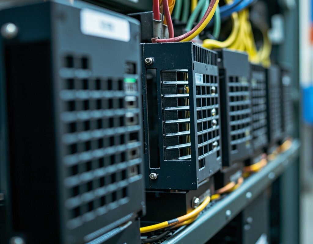
Introduction: Why Standard Power Cable Fails with VFDs
Variable frequency drives deliver remarkable energy efficiency but generate severe electromagnetic interference (EMI). Standard THHN/THWN power cable is completely inadequate for VFD applications. Using conventional cable between a VFD and its motor leads to:
- Motor bearing fluting — EDM damage reducing bearing life by 90%
- EMI/RFI interference disrupting PLC communications and sensor signals
- Ground loop currents causing nuisance trips
- Insulation stress from high dV/dt voltage spikes
- Common-mode noise propagating throughout electrical distribution
The solution: purpose-designed VFD cable (inverter duty cable) addressing these challenges through specialized geometry, advanced shielding, and optimized insulation.
Iflexcable manufactures comprehensive VFD power cables meeting IEC 61800-3, NEC Article 430, and UL standards worldwide.
The Physics of VFD Noise
PWM Switching Side Effects
Modern VDFs use Pulse Width Modulation switching (typically 2–20 kHz) creating several phenomena:
1. High dV/dt Voltage Transients
Each IGBT switch generates rise times of 50–10,000 V/µs, creating:
- Voltage reflections doubling peak voltage at motor terminals (up to 2× DC bus voltage)
- Capacitive coupling through motor winding insulation accelerating aging
- Partial discharge when voltages exceed corona inception threshold
VFD cable with enhanced insulation dielectric strength (≥2000V impulse rated) significantly mitigates this risk.
2. Common-Mode Current Generation
Asymmetrical switching produces common-mode voltage driving currents through parasitic capacitances. Typical levels range from hundreds of mA to several amps—currents flowing through motor bearings (causing fluting), finding return paths through signal cables, and injecting noise into facility ground grids.
Properly designed symmetrical VFD cable with effective shielding reduces common-mode currents by providing controlled return path directly back to the drive.
3. Bearing Damage Mechanisms
| Bearing Damage Type | Cause | Effect |
|---|---|---|
| Shaft Voltage Buildup | Capacitive coupling stator→rotor | Spark discharge through bearings |
| Circulating Currents | Asymmetrical flux linking shaft | Arcing at bearing interfaces |
Studies show over 50% of inverter-fed motor failures involve bearing damage from inadequate cabling. Shielded VFD cable can reduce shaft voltages by 80–95%.
VFD Cable Design Anatomy
Conductor System
VFD cable conductors differ fundamentally from standard power cable:
- Stranding: Class 5 or finer (min. 19 strands for AWG 14). Fine stranding reduces skin effect losses at PWM frequencies.
- Size Derating: Ampacity may need 15–25% derating due to skin/proximity effects at switching frequencies.
- Symmetrical Geometry: Phase + ground conductors positioned symmetrically (120° spacing) ensuring balanced capacitive coupling.
Insulation System
| Material | Dielectric Strength | Temp Rating | dV/dt Capability | Corona Resistance |
|---|---|---|---|---|
| EPR | Very Good | -55°C~+105°C | Excellent | Excellent |
| Silicone | Good | -55°C~+150°C | Fair | Poor |
| PVC (Special) | Moderate | -15°C~+75°C | Poor | None |
Recommendation: XLPE-insulated VFD cable offers the best combination of dielectric strength, thermal stability, and cost-effectiveness. For extreme temps, EPR provides superior low-temp flexibility.
Shielding: The Most Critical Component
VFD cable shielding serves two functions:
- Contain EMI Emissions: Prevent cable radiating energy interfering with nearby equipment
- Provide Controlled Ground Return: Give common-mode currents low-inductance path back to drive chassis ground
| Shield Type | Coverage (%) | Transfer Impedance @1MHz | Flexibility | Cost |
|---|---|---|---|---|
| Single braid | 85–95% | 5–20 mΩ/m | Good | Medium |
| Double braid | 95–99% | 1–5 mΩ/m | Fair | High |
| Al/PET tape + braid | 98–100% | 0.5–3 mΩ/m | Fair | Med-High |
| Al tape + braid + drain | 99%+ | <0.5 mΩ/m | Fair | High |
Iflexcable Recommendation: For most VFD cable applications, Al-polyester foil (100%) overlaid with tinned copper braid (≥85%) provides optimal EMI containment with acceptable flexibility, achieving transfer impedance below 10 mΩ/m across the critical 1–30 MHz band.
Grounding Configuration
| Configuration | Description | When Required |
|---|---|---|
| 3C + 3G symmetrical (recommended) | Three phases + three symmetrical grounds | Long runs >25m, carrier freq >6kHz, sensitive equipment nearby |
| 4C symmetrical (premium) | Four identical conductors in quadrature | Ultimate balance; less common |
Standards Compliance
IEC 61800-3 (Global VFD EMC Standard)
| Parameter | Class A (Industrial) | Class B (Residential) |
|---|---|---|
| Cond. emissions (0.5–30MHz) | 73 dBµV | 56 dBµV |
| Rad. emissions (30–230MHz) | 40 dBµV/m @10m | 30 dBµV/m @10m |
| Rad. emissions (230MHz–1GHz) | 47 dBµV/m @10m | 37 dBµV/m @10m |
Properly shielded inverter duty cable is typically essential for Class B compliance.
NEC Article 430 (US National Electrical Code)
Key requirements relevant to VFD cable:
- 430.122(B): Grounding conductors required in VFD circuit wiring
- 430.247: Recognizes inverter-duty rated conductors
- 250.118(11): Lists acceptable equipment grounding conductor types including shields
Installation Best Practices
Routing and Separation
| Circuit Type | Min Separation | Recommended |
|---|---|---|
| Data networks (Ethernet, Fieldbus) | 300 mm | 1000 mm |
| Low-level sensors (<1V) | 450 mm | 1500 mm |
| Other VFD cables | 100 mm | 200 mm |
Routing principles:
- Route VFD power cables in steel conduit or dedicated tray sections
- Cross perpendicular (90°) if unavoidable—never parallel
- Keep runs as short as possible (every meter adds antenna length)
Termination Techniques
Drive End: Strip carefully without nicking insulation. Connect shield via 360° clamp (not pigtail!). Ensure all grounds connect to drive ground bar. Torque per manufacturer spec (1.5–3 N·m typical).
Motor End: Same procedure. Connect shield to motor frame via 360° clamp. CRITICAL: Install shaft grounding ring if motor lacks insulated bearing option. For runs >50m, consider dV/dt filter at motor terminals.
Common Mistakes
| Mistake | Consequence | Correct Approach |
|---|---|---|
| Pigtail ground (6″ wire) | Adds inductance; defeats HF shielding | Use 360° clamp or EMC gland |
| Same conduit as 24VDC controls | Capacitive coupling induces noise | Separate conduit or armored VFD with integrated signals |
| Undersized ground | Cannot carry CM current safely | Size grounds ≥ phase conductors |
Product Recommendations
Light Industrial (Pumps, Fans, Conveyors) — Iflexcable VFD-L Series
- XLPE insulated, PVC jacketed; Al tape + TC braid shield (90%); 3-phase + 1-ground; ≤8 kHz carrier freq; -20°C to +90°C; IEC Class A compliant
Heavy Manufacturing (CNC, Presses) — Iflexcable VFD-Pro Series
- XLPE/PUR jacketed; dual-layer shield (Al tape + double braid, 97%); 3-phase + 3-symmetrical-ground; 2000V impulse-rated XLPE; -40°C to +105°C; IEC Class B compliant
Extreme Environment (Marine, Mining) — Iflexcable VFD-Xtreme Series
- EPR insulated; TPU outer jacket UV-stabilized; triple-shield (Al tape + Cu braid + Cu tape, 99.5%+); IP68 submersible capable; -50°C to +125°C
Conclusion
The incremental premium of proper VFD cable over standard power cable ranges 1.5–3× depending on gauge and complexity. Against this modest increase consider prevented costs: bearing replacement ($500–$5000 per occurrence), downtime ($2,000–$50,000/hour), troubleshooting labor ($100–$200/hour). For any new VFD installation, Iflexcable recommends investing in properly specified variable frequency drive cable from the outset.
Keywords used naturally: VFD cable, variable frequency drive cable, inverter duty cable, VFD power cable, EMC cable, symmetrical grounding cable, VFD motor cable, VFD shielding, VFD bearing protection