
Torsion Resistant Anti-Twist Cable Guide: High-Twist Robotics, Robot 7th Axis & Continuous Rotation Applications
Introduction: The Unique Challenge of Torsional Stress While most flexible cable applications involve bending (as in drag chains), a significant subset involves torsional stress—twisting or rotational deformation placing entirely different demands on…
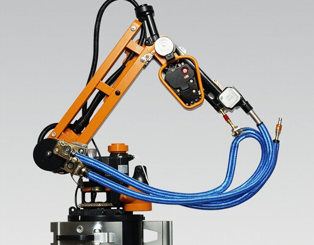
Introduction: The Unique Challenge of Torsional Stress
While most flexible cable applications involve bending (as in drag chains), a significant subset involves torsional stress—twisting or rotational deformation placing entirely different demands on construction. Torsion resistant cables (anti-twist, anti-torque, rotary cables) must accommodate continuous or repetitive rotation while maintaining electrical integrity.
Applications requiring torsion resistant cable include:
- Robot 7th axis (turntable) where the bundle twists as turntable rotates
- Robotic wrist joints with ±180°+ torsion per articulation cycle
- Wind turbine pitch control requiring 90°+ twist per actuation
- Cranes and hoists with multi-directional pendant cable torsion
- Automated assembly with rotary index tables
- Medical devices (surgical tools, CT gantry) with rotating components
Standard high flex cable designed for bending fails catastrophically in torsion—often within tens of thousands of cycles. This guide explains why and how to specify proper anti-twist cable.
Understanding Torsion vs Bending Stress
| Parameter | Pure Bending (E-Chain) | Pure Torsion (Rotation) |
|---|---|---|
| Stress distribution | Non-uniform (max at surface) | More uniform |
| Damage mechanism | Fatigue breakage at outer radius | Helical unwinding/corkscrewing |
| Failure mode | Conductor strand breakage | Conductor untwisting, insulation delamination |
| Countermeasure | Fine stranding + sliding layers | Counter-helix + torque-balanced pairs |
Quantifying Torsion Requirements
Twist Angle (Degrees per Meter):
| Application Type | Typical Twist Angle |
|---|---|
| Moderate (robot wrists) | ±180–360°/m |
| Heavy (7th axis positioners) | ±360–720°/m |
| Extreme (centrifuges, winders) | >±720°/m |
Total Cycles Required:
| Category | Cycles | Life Equivalent |
|---|---|---|
| Standard robotics | 500K–2M | 5–10 years |
| High-speed automation | 5M–15M | 5–10 years intensive |
| Extreme (24/7) | 20M–30M+ | Premium only |
Anti-Torsion Construction Technologies
Counter-Helix (Reverse-Lay) Design — THE Foundation
Adjacent conductor layers twisted in opposite helical directions:
Layer 1 (outer): <<<<<< Left-hand lay
Layer 2 (inner): >>>>>> Right-hand lay

Applied clockwise torque -> Layer1 unwinds, Layer2 tightens
-> Forces balance internally -> Minimal stress on conductors
| Parameter | Effect on Performance |
|---|---|
| Number of balanced pairs | More pairs = better compensation |
| Central element stiffness | Stiffer core reduces angular displacement |
Torque-Balanced Pairs
For signal-carrying anti-twist cable: individual twisted pairs engineered so net torsional moment approaches zero under strain. Essential for encoder feedback where twist would corrupt differential timing.
Central Strength Member Integration
| Material | Torsional Stiffness | Flexibility | Best For |
|---|---|---|---|
| Fiberglass E-glass | High | Good | High-temp env |
| Steel wire rope | Extremely high | Poor | Static/high-load only |
Recommendation: Aramid central member provides optimal balance.
Failure Modes Specific to Torsion
Corkscrew Deformation (Helical Kinking)
Progression: Slight permanent set → visible spiral pattern → kinks → interference → conductor breakage. Prevention: Use genuine counter-helix anti-torque cable.
Insulation Delamination
Inadequate adhesion under shear exceeding interlayer bond strength. Prevention: Bonded insulation; higher shear modulus materials.
Pair Untwisting
Twisted-pair “unlaying” under repeated torsion causing impedance changes and NEXT degradation. Prevention: Shorter initial lay lengths; torque-balanced design.
Application-Specific Guidance
Robot 7th Axis Positioner Cabling
| Requirement | Value |
|---|---|
| Cycle freq | Every 5–30 seconds |
| Cable count | 10–25 conductors in harness |
| Environment | Welding spatter, heat, oil mist |
| Service life target | 5–10 million cycles |
→ Iflexcable TRV-Series: Multi-conductor 7th axis cable with counter-helix pairs, aramid central member, PUR jacket, individually shielded data pairs.
Wind Turbine Pitch Control
| Challenge | Spec |
|---|---|
| Twist range | ±95° per pitch change |
| Vibration | Continuous broadband |
| Accessibility | Extremely difficult (crane needed) |
→ Iflexcable WT-Pitch Series: Extended cold-flex (-60°C), double-layer counter-helix, UV-stabilized jacket, SPD option, 20+ year design life.
Robotic Wrist/Internal Arm Cabling
Combined loading challenge:
- Torsion: Extreme (±180°+/move)
- Bending: High (tight radius)
- Axial load: Moderate
- Crushing: Moderate
→ Iflexcable RW-Series (Robot Wrist): Ultra-mini OD (3–8mm), PTFE/FEP insulation, SS braided armor, validated for combined-stress testing, >5M cycles.
Testing Protocol (Iflexcable Internal)
| Step | Condition | Duration |
|---|---|---|
| Static torsion | ±360°/m hold 30min | No set >5° |
| Dynamic cycling | ±180°/m @ 0.5Hz | 1M std / 5M premium |
| Combined torsion+flex | ±90°/m + bend 10×OD @0.3Hz | 500K cycles |
| Post-test verification | Continuity, IR, capacitance | Within 10% of initial |
Conclusion
Torsional stress demands purpose-designed anti-twist cable. Standard flex cable is false economy leading to premature failures. Iflexcable’s torsion resistant portfolio spans compact robot wrist cables (3mm) to large 7th axis harnesses (25mm+), all validated through combined-stress testing.
Keywords used naturally: torsion resistant cable, anti-twist cable, robot torsion cable, 7th axis cable, anti-torque cable, rotary cable, continuous rotation cable