
CNC Machining Center Cable
Introduction: The Electrical Backbone of Precision Manufacturing CNC (Computer Numerical Control) machining centers represent the pinnacle of automated metalworking—achieving positioning accuracy measured in microns while removing material at rates up to several…
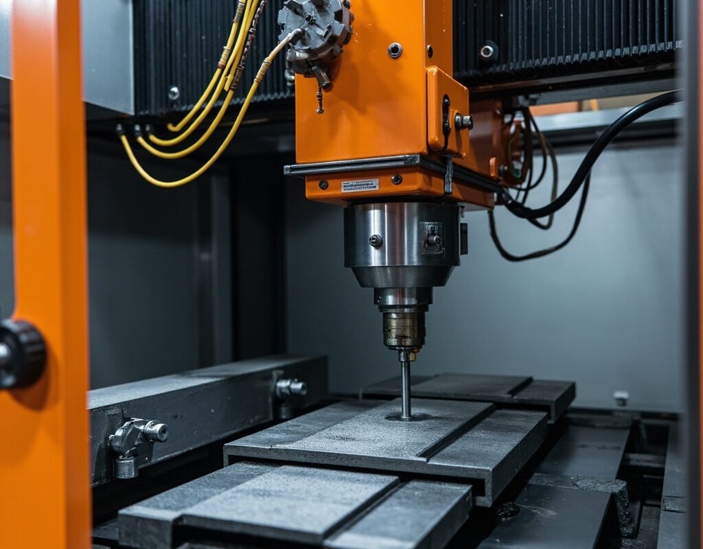
Introduction: The Electrical Backbone of Precision Manufacturing
CNC (Computer Numerical Control) machining centers represent the pinnacle of automated metalworking—achieving positioning accuracy measured in microns while removing material at rates up to several hundred cubic centimeters per minute. This extraordinary precision depends entirely on the electrical infrastructure connecting drives, motors, encoders, sensors, and controllers—and specifically on the quality of CNC machine cable throughout the system.
Consider what’s at stake:
- Positioning accuracy: A noisy encoder feedback cable can introduce position error exceeding the machine’s tolerance band → scrapped parts
- Spindle performance: Marginal spindle motor cable causes voltage drop reducing available torque at critical cutting speeds → poor surface finish or tool breakage
- Uptime: Drag chain cable failure in a machine tool axis stops a $200K–$2M machine dead in its tracks → $500+/hour lost production plus emergency repair premiums
- Coolant system: Coolant-resistant cable failure in the flood-cooled work envelope causes shorts and potential fire hazard
Iflexcable has supplied CNC cable solutions to machine tool builders and retrofitters worldwide, covering every aspect from drag chain cable assemblies through precision encoder feedback to high-power spindle motor cables.
CNC Machine Electrical Architecture Overview
Major Subsystems Requiring Specialized Cable
[CNC Controller Cabinet]
        |
        |--- [Servo Drive] === [SERVO CABLE with Power + Encoder Feedback] ===> [SERVO MOTOR + ENCODER]
        |                                                              |
        |--- [Spindle VFD/Drive] === [SPINDLE POWER CABLE] ===> [SPINDLE MOTOR]
        |                                                              |
        |--- [I/O Module] === [SENSOR/ACTUATOR CABLE] ===> [Proximity Sensors, Limit Switches]
        |                                                              |
        |--- [Coolant Pump VFD] === [PUMP CABLE] ===> [Coolant Pump Motor]
        |                                                              |
        +---[All axis cables route through DRAG CHAIN / ENERGY CHAIN]
Axis Count and Complexity
| CNC Type | Typical Axes | Total Cables per Axis | Drag Chain Fill Challenge |
|---|---|---|---|
| 5-axis mill (XYZ+AB) | 5 | 5–9 | Significant |
| Turn-mill (C+Y lathe + live tooling) | 4–6 | 4–8 | Complex (mixed rotary + linear) |
| Multi-spindle auto lathe | 6–16 | 8–20+ | Very high density required |
| Large gantry/bridge mill | 3–5 (long travel) | 3–5 but very LONG cables | Length challenge vs fill |
| Swiss-type screw machine | 6–10 | 12–18 (extremely compact) | Maximum density challenge |
Drag Chain Cable for CNC Machines
Why Dedicated CNC Drag Chain Cable?
Standard “flexible” cable fails quickly in CNC energy chain service:
| Stress Factor in CNC Drag Chain | Severity |
|---|---|
| Coolant/oil mist inside chain | Polymer degradation accelerator |
| Metal chip ingress | Physical cutting/abrasion of jacket |
| VFD-generated EMI from adjacent cables | Signal integrity threat on encoder pairs |
| Variable speed (rapid traverse vs feed) | Wide velocity range challenges damping design |
| 3-shift operation (24/7) | Compresses lifetime into fewer calendar years |
CNC-Specific Drag Chain Cable Requirements
| Parameter | CNC Machine Requirement | General E-Chain Spec |
|---|---|---|
| Chip/abrasion resistance | HIGH PRIORITY | Low-medium |
| Shielding for encoders | Individual pair shield essential | May be overall only |
| Conductor stranding | Class 6 minimum; Class 7 preferred | Class 5 acceptable |
| Bend radius | 10–12x OD typical (space-constrained) | 12–15x typical |
| Temperature range | -10C to +80C (with coolant heat soak) | -25C to +80C |
| Flame retardance | IEC 60332-1 required (machine tools) | Often not specified |
| Service life target | 5–10 years (matches machine life) | 3–7 years typical |
Iflexcable CNC-DC Series (CNC Drag Chain Cable):
- PUR outer jacket with coolant/oil resistance additives
- Individual twisted-pair shielding for each encoder channel (aluminum foil + tinned braid)
- Hybrid constructions combining servo power + feedback in optimized geometry
- Class 7 extra-fine stranding for maximum flex endurance
- Validated >15 million stroke cycles under simultaneous coolant spray
- Available in round and flat (oval) profiles for space optimization
Spindle Motor Cable
Spindle Drive Power Levels
| Spindle Type | Typical Power | Current Range | Voltage | Cable Challenge |
|---|---|---|---|---|
| Milling spindle | 3–30 kW | 8–65 A | 400/480V 3ph | Significant current; VFD-fed |
| High-speed spindle | 10–50 kW | 25–110 A | 480V 3ph | High-frequency VFD output (up to 1000Hz carrier) |
| Torque motor spindle | 5–75 kW | 15–150 A | 300–480V | Combined torque/speed drive |
High-Frequency VFD Output Concerns
Spindle VFDs often use carrier frequencies of 4–16 kHz (vs 2–4 kHz for general-purpose drives). Higher carrier frequency means:
- Higher dV/dt stress on cable insulation (steeper voltage transitions)
- More capacitive coupling between conductors (increased ground leakage current)
- Higher EMI emission amplitude (broader harmonic spectrum)
- Increased skin effect losses in conductors at switching frequency
Spindle motor cable must be explicitly rated for VFD service with adequate margin above the specific carrier frequency. Using standard power cable is NOT acceptable.
Iflexcable SPINDLE-Series CNC Spindle Cable:
- Reinforced XLPE insulation rated 2000V impulse withstand
- Triple-ground configuration (3-phase + 3-symmetrical-ground) for highest-drive applications
- Dual-layer shielding (Al/PET foil + double tined copper braid) achieving 97% coverage
- Flexible construction (Class 6 stranded) accommodating spindle head movement
- Oil/coolant resistant jacket for through-coolant-trench installations
- Sizes from 4 mm2 to 95 mm2 covering spindles up to ~75 kW
Encoder Feedback Cable for CNC
Position Feedback Types in CNC
| Feedback Technology | Resolution Typical | Cable Requirements | Common CNC Use |
|---|---|---|---|
| Absolute optical encoder (SSI) | 17–23 bit (131k–8M counts) | Synchronous serial (Clk+,Clk-,Data+,Data-) shielded | Modern mid-range |
| EnDat 2.2 (single/multi-turn) | Up to 25-bit | 6–8 wire EnDat-specific; impedance controlled | Siemens/Simodrive systems |
| HIPERFACE DSL (2-wire digital) | Up to 32-bit | 2-wire power+data combined; special cable required | Bosch Rexroth, newer designs |
| Linear scale (glass/optical) | 0.05–5 um resolution | Optical fiber or special electrical | Ultra-high-precision applications |
| Resolver (analog) | Coarse (12-16 bit) | 3-wire (sin+,cos-, excitation+) | Heavy-duty spindles; harsh env |
Encoder Cable Best Practices for CNC
- Separate from power cables: Route encoder feedback cable in dedicated drag chain compartment or separate conduit — NEVER bundle directly with servo power conductors
- Maintain consistent pairing: Never split differential pairs (keep A and /A together always)
- Use 360-degree shield termination: At BOTH encoder and controller ends via metal clamp or EMC gland — never pigtail
- Reserve slack for maintenance: Leave service loop at encoder end for replacement without disturbing alignment calibration
- Match cable type to encoder spec: Using generic cable instead of manufacturer-recommended encoder cable voids warranty AND degrades accuracy
Iflexcable ENC-CNC Series: Protocol-specific CNC encoder cables
- ENC-INC: Incremental (6-wire differential, A/B/Z + complements)
- ENC-SSI: Synchronous Serial Interface (4-wire, Clk/Data pairs)
- ENC-ENDAT: EnDat 2.1/2.2 compliant (6–8 wire, matched-length sets)
- ENC-HDSL: HIPERFACE DSL 2-wire digital
- All versions: Individually shielded twisted pairs, matched propagation delay, PUR jacket (coolant resistant)
Coolant System Cabling
Coolant Pump and Control
CNC machine coolant systems present combined hazards:
| Hazard | Mitigation in Cable Selection |
|---|---|
| Cutting fluid chemical aggressiveness | Chemical-resistant jacket (PUR or TPU) |
| Submerged operation possible | Submersion-rated construction (IP68 when terminated properly) |
| Chip debris impact | Abrasion/tear resistant jacket material |
| Proximity to VFD-driven pump | Shielded variant if long run (>5m) |
Recommendation: Use oil-resistant flexible cable (similar to VFD cable but often lower voltage/current for small pumps) for all coolant system components.
Installation Guidelines for CNC Retrofits
When replacing failed CNC machine cable in existing equipment:
- Document original routing photographically before removal
- Measure total length including service loops — don’t cut short
- Match conductor size EXACTLY — undersized replacement fails faster; oversized may not fit terminals
- Verify shield continuity on encoder cables after installation (<0.1 ohm end-to-end)
- Perform dry-run axis movement before production restart — check for interference at full travel limits
- Record new cable part number and installation date in machine maintenance log
Conclusion
CNC machining center cable infrastructure is too important to treat as an afterthought. The difference between a well-specified CNC drag chain cable assembly and a generic “flexible cable” retrofit can determine whether your $500K machine produces micron-perfect parts or generates scrap.
Iflexcable offers comprehensive CNC cable solutions: CNC-DC Series drag chain cable, SPINDLE-Series power cables, and ENC-CNC Series encoder feedback cables—all validated for the combined stresses of coolant exposure, high-cycle motion, and EMI-rich environments found in modern machining centers.
Contact our CNC application specialists with your machine model, axis count, and spindle specifications—we’ll recommend the complete cable package.
Keywords used naturally: CNC cable, machining center cable, CNC drag chain cable, spindle motor cable, CNC encoder cable, milling machine cable, CNC router cable