
Industrial Motor Connection Cable & Power Cable
Introduction: The Arteries of Industrial Power Electric motors consume approximately 45% of global electricity, rising above 70% in industrial settings. Every motor depends on motor connection cables delivering electrical energy from drives,…
Introduction: The Arteries of Industrial Power
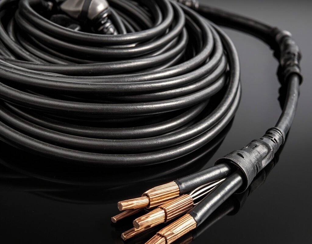
Electric motors consume approximately 45% of global electricity, rising above 70% in industrial settings. Every motor depends on motor connection cables delivering electrical energy from drives, starters, or distribution panels to motor terminals.
While sizing might seem straightforward (“just size the wire for current”), proper motor cable engineering accounts for:
- Starting surges reaching 600–800% FLA for DOL-started motors
- Harmonic currents from VFD-fed motors (5th, 7th, 11th, 13th order)
- Thermal cycling between ambient idle and full-load heating (ΔT 40–80°C)
- Environmental assault from oil, coolant, abrasion, UV, mechanical impact
- Voltage drop constraints affecting torque production and starting
- Code/regulatory compliance varying by jurisdiction and installation type
This guide provides technical depth for informed motor connection cable decisions—from fractional HP pumps to multi-megaward mining conveyors.
Conductor Sizing Methodology
Base Ampacity Tables
| Copper Size | AWG | mm² | Ampacity @75°C (NEC) | @90°C (IEC) |
|---|---|---|---|---|
| 16 | 16 | 1.31 | 18 A | — |
| 14 | 14 | 2.08 | 25 A | — |
| 12 | 12 | 3.31 | 35 A | — |
| 10 | 10 | 5.26 | 50 A | 57 A |
| 8 | 8 | 8.37 | 70 A | 83 A |
| 6 | 6 | 13.3 | 95 A | 114 A |
| 4 | 4 | 21.2 | 125 A | 148 A |
| 2 | 2 | 33.6 | 175 A | 208 A |
| 1/0 | 0000 | 53.5 | 225 A | 267 A |
| 2/0 | 00 | 67.4 | 275 A | 326 A |
| 3/0 | 000 | 85.0 | 325 A | 385 A |
| 4/0 | 0000 | 107.2 | 380 A | 452 A |
| 250 kcmil | — | 127 | 405 A | 482 A |
| 350 kcmil | — | 177 | 470 A | 559 A |
| 500 kcmil | — | 253 | 545 A | 648 A |
Derating Factors That Reduce Ampacity
Never use base ampacity without applying derating factors!
| Derating Category | Condition | Multiplier |
|---|---|---|
| Conductor bundling | 4-6 conductors | 0.80 |
| 7-9 conductors | 0.70 | |
| 10-20 conductors | 0.50 | |
| Continuous load (≥3 hours) | Per NEC 215.2 | Base × 125% minimum |
| VFD harmonic heating | PWM carrier frequency effect | 0.85–0.95 depending on freq |
| High altitude | >1000m elevation | 0.99 per 100m above 1000m |
Temperature Derating Table (NEC):
| Ambient Temp (°C) | 60°C Column | 75°C Column | 90°C Column |
|---|---|---|---|
| 31–35 | 0.91 | 0.94 | 0.96 |
| 36–40 | 0.82 | 0.88 | 0.91 |
| 41–45 | 0.71 | 0.82 | 0.87 |
| 46–50 | 0.58 | 0.75 | 0.82 |
| 51–55 | 0.41 | 0.65 | 0.76 |
| 56–60 | — | 0.58 | 0.71 |
Example Calculation: 10 HP motor (28A FLA), 40°C ambient, 4 conductors in conduit, VFD-driven:
- Base ampacity (AWG 10, 90°C): 57 A
- Ambient derate (40°C): 57 × 0.91 = 51.9 A
- Bundle derate (4 cond): 51.9 × 0.80 = 41.5 A
- Continuous load factor: 28 × 1.25 = 35 A required → AWG 10 OK (41.5 > 35)
- VFD harmonics safety margin: 41.5 × 0.90 = 37.4 A → still OK but marginal
Voltage Drop Analysis
Voltage drop directly affects motor performance. NEMA MG1 recommends maximum 5% total voltage drop from service entrance to motor terminals (with ≤3% in feeder branch).
Voltage Drop Formula
VD (%) = (2 × L × I × (R×cos(φ) + X×sin(φ))) / 1000 × V × 100

Where:
  L   = One-way cable length (meters)
  I   = Full-load current (amps)
  R   = Conductor resistance (Ω/km)
  X   = Reactance (Ω/km)
  φ   = Phase angle (power factor angle)
  V   = System line-to-line voltage (volts)
Quick Reference: Voltage Drop % per 100ft (480V system)
| Wire AWG | @ 10A | @ 20A | @ 30A | @ 50A | @ 75A | @ 100A |
|---|---|---|---|---|---|---|
| 12 | 1.0% | 2.0% | 3.0%* | — | — | — |
| 10 | 0.63% | 1.25% | 1.88% | 3.1%* | — | — |
| 8 | 0.39% | 0.78% | 1.18% | 1.96% | 2.9%* | — |
| 6 | 0.25% | 0.50% | 0.74% | 1.23% | 1.86% | 2.47%* |
| 4 | 0.15% | 0.31% | 0.46% | 0.77% | 1.16% | 1.54% |
| 2 | 0.10% | 0.19% | 0.29% | 0.49% | 0.73% | 0.97% |
| 1/0 | 0.06% | 0.12% | 0.18% | 0.31% | 0.46% | 0.61% |
(* exceeds recommended 3%)
Practical rule of thumb: For servo motor cable applications where precise torque response is critical, limit voltage drop to 2% maximum rather than the general 3–5%.
Insulation Systems for Motor Cables
Temperature Rating Classes
| Insulation Class | Max Operating Temp | Materials | Typical Life at Rated Temp | Hours to Failure @ +10°C Over |
|---|---|---|---|---|
| Class F (155°C) | 155°C | XLPE, EPR crosslinked | 20,000 hours | Halved |
| Class H (180°C) | 180°C | Silicone rubber, glass-fiber | 20,000 hours | Halved |
| Class N (200°C) | 200°C | PTFE, polyimide | 20,000 hours | Halved |
| Class R (220°C) | 220°C | Special ceramics/composites | 20,000 hours | Halved |
The “Rule of 10”: For every 10°C above rated temperature, insulation life is approximately halved. This makes proper thermal management critical for motor lead cable longevity.
Common Insulation Material Comparison
| Material | Temp Range | Moisture Resistance | Oil Resistance | Flexibility | Cost Index |
|---|---|---|---|---|---|
| XLPE | -65~+150°C | Excellent | Good | Fair | ★★☆ (Med-Low) |
| EPR | -55~+150°C | Excellent | Very Good | Very Good | ★★★ (Medium) |
| Silicone | -60~+180°C | Excellent | Fair | Excellent | ★★★★ (High) |
| PTFE/Teflon | -65~+260°C | Outstanding | Outstanding | Poor (stiff) | ★★★★★ (Very High) |
For most industrial AC motor cable applications, XLPE insulation offers the best balance of properties. For servo motor cable requiring enhanced flexibility, EPR is preferred despite higher cost.
Motor Cable Types by Application
1. AC Induction Motor Power Cable (DOL or Soft-Start)
Characteristics: Fixed installation (no continuous flex), high starting current tolerance, relatively long service life expected (20+ years).
Recommended construction:
- Conductors: THHN/THWN-2 stranded copper (Class B stranding acceptable)
- Insulation: XLPE (rated for motor’s insulation class + margin)
- Outer jacket: PVC (general) or PVC/nylon (for physical protection)
- Grounding: Equipment grounding conductor per NEC Table 250.122
- Voltage rating: 600V or 1000V (higher for larger motors)
Special note: For motors fed through variable frequency drives, see Section below on VFD-rated motor cable—standard THHN is NOT adequate.
2. Servo Motor Power Cable (Continuous Motion)
Characteristics: Continuous dynamic motion (often through energy chains), combined power+feedback in some designs, EMI-sensitive environment due to resolver/encoder feedback.
Recommended construction:
- Conductors: Class 6 fine-stranded copper (for flex applications)
- Insulation: XLPE or EPR (flexibility + thermal rating)
- Shielding: Overall foil + tinned braid (EMI containment mandatory near sensitive controls)
- Jacket: PUR or TPU (oil/abrasion resistant, flexible)
- Optional: Integrated encoder feedback pairs within same cable (hybrid design)
Iflexcable Servo-Power Series combines power conductors with encoder feedback pairs in optimized hybrid geometry, reducing cable count and simplifying routing.
3. DC Motor Power Cable
Characteristics: May carry both armature current and field current (separately excited machines); higher ripple current content than pure AC applications; potential for ground fault currents in ungrounded DC systems.
Key considerations:
- DC resistance (not just AC impedance) determines voltage drop and heating
- Ripple current frequency content may require additional skin-effect consideration
- Some DC motor applications involve reversing polarity (plugging) requiring robust insulation
- Brush commutation generates broadband EMI that cable shielding must contain
4. Submersible Pump Motor Cable
Characteristics: Fully immersed operation, direct water contact, often deep vertical runs with significant weight loading, agricultural/well/municipal water applications.
Required features:
- Submersion-rated jacket (typically HDPE over PVC or EPDM)
- Pressure-resistant construction (for deep wells)
- Grounding wire for motor frame bonding (critical for personnel safety)
- Abrasion-resistant outer layer (well casing contact during installation)
- UV-resistant (above-ground portions)
Iflexcable SUB-Series: HDPE-jacketed, pressure-tested to 300psi, available in flat (2D) and round (3D) configurations for well pump applications up to 1000 ft depth.
Protection Coordination
Motor Circuit Protection Hierarchy
[Supply] → [Disconnect] → [Short-Circuit Protection] → [Overload] → [Motor Cable] → [Motor]
                    [Branch OCP]     [Motor Overload Relay]    [Conductors]    [Terminals]
Key Protection Considerations for Cable Selection
| Protection Device | What It Protects | Interaction with Cable Sizing |
|---|---|---|
| Motor Overload Relay | Thermal overload (not short-circuit) | Set to FLA range; cable must carry 125% FLA continuously |
| Ground Fault Protection | Phase-to-ground faults | Determines minimum ground conductor size |
| Phase Loss Monitor | Single-phasing damage | Prevents motor (and cable) damage from running on two phases |
| VFD built-in protection | Drive self-protection + some motor protection | Does NOT replace proper cable selection |
Short-Circuit Withstand Rating
Every motor connection cable has a short-circuit current withstand rating based on its conductor size, insulation material, and duration before damage occurs:
I_sc_withstand ≈ K × A / √t

Where:
  K = Material constant (143 for Cu/PVC, 176 for Cu/XLPE, 234 for Cu/PP)
  A = Cross-sectional area (mm²)
  t = Fault duration (seconds)
Example: 10 mm² Cu/XLPE cable, 1-second fault:
- I_sc = 176 × 10 / √1 = 1,760 A withstand for 1 second
Ensure upstream protective device clears faults within the cable’s time-current withstand capability.
Installation Standards and Practices
Conduit Fill Requirements (NEC Chapter 9 Table 1)
| Trade Size (in) | Max Fill % (1 cable) | Max Fill % (2 cables) | Max Fill % (3+ cables) |
|---|---|---|---|
| ¾” (21mm) | 53% | 31% | 40% |
| 1″ (27mm) | 53% | 31% | 40% |
| 1¼” (35mm) | 53% | 31% | 40% |
| 1½” (41mm) | 53% | 31% | 40% |
| 2″ (53mm) | 53% | 31% | 40% |
Support Spacing Requirements
| Cable Type | Max Support Interval (Horizontal) | Max Support Interval (Vertical) |
|---|---|---|
| MC cable (metal-clad) | 1.5 m (4.5 ft) | — |
| Individual conductors in conduit | N/A (supported by conduit) | N/A |
| Open single-conductor cable | Every 1.2 m (4 ft) | Every 30 m (100 ft) |
| SE/SER service entrance | Every 1.2 m (4 ft) | — |
Environmental and Special-Purpose Motor Cables
High-Temperature Motor Cable (Foundry, Kiln, Oven Applications)
Operating temperatures exceeding 105°C demand specialized materials:
| Temperature Range | Insulation | Jacket | Application |
|---|---|---|---|
| 150–200°C | Silicone rubber | Fiberglass/silicone | Ceramic kilns, glass manufacturing |
| 200–250°C | PTFE, FEP | Stainless steel braid | Metal treating furnaces |
| 250–400°C | Mica-glass tape + ceramic | Refractory fiber | Extreme furnace applications |
Iflexcable HT-Motor Series: Available up to 400°C continuous rating with ceramic-insulated, stainless-overbraided construction.
Outdoor/UV-Resistant Motor Cable
For outdoor pump drives, HVAC condenser fans, and exterior-mounted equipment:
- Black UV-stabilized PVC or HDPE jacket (minimum 3% carbon black content for UV blocking)
- Sunlight-resistant listing (UL 854 for service entrance types)
- Moisture-resistant insulation (XLPE preferred over standard PVC)
- Rodent-resistant options available (jacket additives or metal armor)
Marine and Offshore Motor Cable
Shipboard, offshore platform, and dockside motor applications require:
- ABS, DNV-GL, Lloyd’s Register approval
- Oil/mud/fuel resistant jacket (CSA CZR type or equivalent)
- Flame retardant, low smoke zero halogen (LSZH)
- Wet-location rated (submersion capability for bilge applications)
- Corrosion-resistant terminations (tinned conductors, plated hardware)
Iflexcable MAR-Series: DNV-GL approved, IEC 60092 compliant, available in armored and unarmored versions.
Conclusion: Building Reliable Motor Power Infrastructure
Proper motor connection cable selection involves far more than picking a wire gauge from a table—it requires understanding starting characteristics, environmental conditions, code requirements, protection coordination, and lifecycle economics. An underspecified cable leads to premature failure and costly downtime; an overspecified cable wastes capital that could be better invested elsewhere.
Iflexcable‘s application engineers are ready to assist with motor cable specifications for any application—from fractional horsepower fan motors to megaward-class industrial drives. Contact us for detailed technical consultation and sample evaluation programs.
Keywords used naturally: motor connection cable, motor power cable, servo motor cable, AC motor cable, DC motor cable, industrial motor cable, motor lead cable, motor cable ampacity, motor cable sizing