
Industrial Robot Cable Selection Guide
Introduction: Why Industrial Robot Cable Selection Matters More Than Ever In the rapidly evolving landscape of Industry 4.0 and smart manufacturing, the industrial robot cable infrastructure has become a critical determinant of…
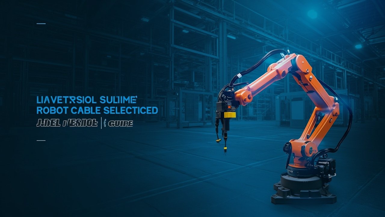
Introduction: Why Industrial Robot Cable Selection Matters More Than Ever
In the rapidly evolving landscape of Industry 4.0 and smart manufacturing, the industrial robot cable infrastructure has become a critical determinant of overall system reliability. According to recent industry data, up to 35% of unplanned downtime in robotic workcells can be traced directly to cable or connector failures—a statistic that underscores the importance of proper cable specification from the outset.
Whether you’re deploying a 6-axis robot cable system for automotive body welding, configuring a SCARA robot cable for high-speed electronics assembly, or integrating collaborative robot cable networks into human-robot collaborative workspaces, understanding the technical nuances of cable selection directly impacts your total cost of ownership (TCO) and mean time between failures (MTBF).
This guide provides an in-depth technical analysis of industrial robot cable selection, covering conductor sizing methodologies, insulation material science, shielding topologies, and real-world application case studies that bridge theory with practical implementation.
Understanding the Anatomy of Industrial Robot Cables
Conductor Architecture: Beyond Simple Wire Gauges
The foundation of any reliable robot power cable lies in its conductor design. Unlike static wiring where solid or minimally-stranded conductors suffice, dynamic robotic applications demand sophisticated stranding architectures:
| Stranding Class | Wire Diameter | Typical Applications | Flex Life Rating |
|---|---|---|---|
| Class 5 (flexible) | 0.02″–0.05″ strands | Lightly moving applications | ~1–2 million cycles |
| Class 6 (highly flexible) | 0.01″–0.03″ strands | Continuous flex, drag chain | ~5–15 million cycles |
| Class 7 (extra fine strand) | <0.01" strands | Torsional, high-speed robot joints | ~20+ million cycles |
For robot arm cable applications involving continuous multi-axis motion, Class 6 or Class 7 stranding is typically mandatory. Fine-stranded conductors—often comprising hundreds of individual copper wires per conductor—distribute mechanical stress across a larger surface area, dramatically reducing individual wire fatigue.
Key technical note: When specifying 6-axis robot cable, the base joint (J1 axis) experiences the highest torsional stress and should use Class 7 conductors with specialized anti-torque core designs. Wrist joints (J4-J6 axes) experience higher-frequency bending but lower torque, making optimized Class 6 stranding often sufficient.
Insulation Materials: Matching Chemistry to Environment
The insulation system of a robot signal cable determines its dielectric performance, thermal limits, and chemical compatibility:
| Material | Max Operating Temp | Dielectric Strength | Chemical Resistance | Best For |
|---|---|---|---|---|
| PP (Polypropylene) | 90°C | 25–30 kV/mm | Good | Thin-wall, space-critical |
| PE/Polyethylene | 75°C | 30–40 kV/mm | Excellent | High-frequency signals |
| XLPE (Cross-linked PE) | 90°C | 35–45 kV/mm | Very Good | Higher voltage, outdoor |
| PUR (Polyurethane) | 80°C | 15–20 kV/mm | Excellent (oil/wear) | Harsh industrial, drag chain |
| TPE (Thermoplastic Elastomer) | 105°C | 18–22 kV/mm | Good | Flexible general-purpose |
| Silicone Rubber | 180°C+ | 20–25 kV/mm | Good | Extreme temperature |
| FEP/PTFE (Fluoropolymer) | 200°C+ | 60–80 kV/mm | Outstanding | Extreme environments |
For most industrial robot cable deployments, TPE-insulated conductors within a PUR jacket represents the optimal balance of flexibility, durability, and chemical resistance for typical factory environments ranging from +5°C to +60°C ambient temperatures.
Shielding Topologies: Protecting Signal Integrity in Noisy Environments
Modern robot control cable systems must contend with electromagnetic interference (EMI) from variable frequency drives (VFDs), welding equipment, servo amplifiers, and switching power supplies. The choice of shielding topology directly impacts both EMI immunity and mechanical flexibility:
Foil Shielding (Aluminum-Polyester Tape):
- Provides 100% coverage at minimal thickness
- Ideal for high-frequency EMI protection (>1 MHz)
- Lower mechanical strength; can tear under repeated flex
- Commonly used in combination with braid shields
- Transfer impedance: typically 10–100 mΩ/m at 1 MHz
Braid Shielding (Tinned Copper Braid):
- Typical coverage: 70–95% depending on weave density
- Superior mechanical strength and flex endurance
- Better low-frequency EMI rejection (<1 MHz)
- Transfer impedance: typically 1–10 mΩ/m at 1 MHz
- Preferred for robot encoder cable and feedback circuits
Combination Shielding (Foil + Braid):
- Offers comprehensive protection across the full frequency spectrum
- Standard requirement for robot data cable carrying Ethernet or fieldbus protocols
- Increases cable diameter by 0.3–0.8mm compared to single-shield options
- Recommended for all articulated robot cable installations near VFDs or welding systems
Power Cable Sizing Methodology
Calculating Correct Gauge for Robot Motor Power
Proper robot power cable sizing requires analyzing multiple factors beyond simple ampacity tables. Here’s the engineering approach:
Step 1: Determine Motor Full Load Current (FLC)
FLC = Motor Rated Power (kW) × 1000 / (√3 × Voltage × Power Factor × Efficiency)

Example: 5 kW AC servo motor @ 400V, PF=0.85, Eff=92%
FLC = 5000 / (1.732 × 400 × 0.85 × 0.92) = 9.24A
Step 2: Apply Derating Factors
Real-world derating factors that reduce effective current capacity:
- Ambient temperature above 30°C: apply IEC 60364-5-52 correction factors (typically 0.71–0.91)
- Bundled cables in conduit: group derating per NEC Table 310.15(C)(16) or IEC 60364-5-52
- Continuous operation (>3 hours): 80% rating factor
- Altitude >1000m: additional derating required
Step 3: Verify Voltage Drop
Maximum recommended voltage drop for industrial robot cable:
- Power circuits: ≤3% at full load
- Control circuits: ≤5%
Voltage drop formula:
VD (%) = (2 × L × I × R × cosφ) / V × 100
Where: L = one-way length (meters), I = current (A), R = conductor Ω/km
Practical Rule of Thumb: For most robot motor power cable runs up to 15 meters in 400V three-phase systems, the following minimum gauges are recommended as starting points:
| Motor Power | Minimum Copper Size (3-phase) | Ground Conductor |
|---|---|---|
| 1.0–2.0 kW | 4×1.5 mm² (AWG 16) | 1×1.5 mm² |
| 3.0–5.5 kW | 4×2.5 mm² (AWG 14) | 1×2.5 mm² |
| 7.5–11 kW | 4×4.0 mm² (AWG 12) | 1×4.0 mm² |
| 15–22 kW | 4×6.0 mm² (AWG 10) | 1×6.0 mm² |
Signal and Data Cable Considerations
Encoder Feedback Cable Design
The robot encoder cable carries position and velocity feedback from motor-mounted encoders back to the servo drive. Signal integrity here is paramount—even minor noise injection can cause position jitter, reduced accuracy, or complete communication loss.
Critical parameters for encoder feedback cable**:
- Characteristic Impedance: Must match encoder output impedance (typically 120Ω for RS-485 differential pairs). Mismatched impedance causes signal reflections.
- Capacitance: Keep below 100 pF/m for incremental encoders; absolute encoders with serial interfaces may require <60 pF/m.
- Twist Rate: Differential pairs should have consistent twist rates of 20–50 twists per meter. Untwisted leads at termination points should not exceed 12mm.
- Crosstalk Attenuation: ≥40 dB between adjacent pairs at 1 MHz for reliable operation.
Communication Protocols and Cable Requirements
Modern robot communication cable must support increasingly demanding protocols:
| Protocol | Data Rate | Cable Requirement | Maximum Length | Notes |
|---|---|---|---|---|
| EtherCAT | 100 Mbps | Cat5e/Cat6, 100Ω | 100m per segment | Real-time Ethernet |
| Profinet RT | 100 Mbps | Cat5e, shielded | 100m | Siemens ecosystem |
| DeviceNet | 500 kbps | Thick/thin coax hybrid | 500m (thick), 300m (thin) | ODVA standard |
| SERCOS III | 100 Mbps | Fiber or Cat5e | 100m (copper) | Motion control specific |
Robot-Specific Application Analysis
6-Axis Articulated Robot Cable Systems
The 6-axis robot cable configuration presents unique engineering challenges due to the kinematic complexity of articulated robots:
Joint-by-joint cable stress profile:
| Axis | Primary Stress Type | Typical Bend Radius | Angular Range | Estimated Cycles/Hour (typical) |
|---|---|---|---|---|
| J2 (Shoulder) | Bending + tension | 100–180mm | ±135° | 400–1,200 |
| J3 (Elbow) | Bending | 80–140mm | ±145° | 600–1,800 |
| J4 (Wrist rotate) | Torsion + bending | 40–80mm | ±350° | 800–2,500 |
| J5 (Wrist bend) | Bending | 30–60mm | ±130° | 1,000–3,000 |
| J6 (Tool flange rotate) | Torsion | 25–50mm | ±720° | 1,500–5,000 |
Design implication: The cumulative annual cycle count for a typical production 6-axis robot cable installation can easily exceed 10 million cycles at wrist joints. This demands cables specifically rated for torsional flex life (TRVL — Twist Rating Value according to VDE 0298 or equivalent).
Collaborative Robot Cable: Safety Meets Flexibility
Collaborative robot cable systems add safety-critical requirements to traditional cobot cable specifications:
- Dual-channel safety circuitry with cross-monitoring
- Force/torque sensor integration (6-axis F/T sensors requiring 12–24 analog channels plus power)
- Emergency stop daisy-chaining (IEC 60204-1 Category 0 stop, Category 1 with braking)
- Hand-guided mode cabling with teach pendant quick-disconnect
- Reduced cable mass to minimize collision injury risk
Best practice: Specify cobot high flex cable products that carry explicit ISO 10218-1/ISO 13849-1 PL-d (Performance Level d) certification for safety-related control system components.
Standards and Compliance Framework
International Standards Applicable to Industrial Robot Cables
When selecting industrial robot cable for global deployment, verify compliance with the following framework:
| Standard | Scope | Key Requirements |
|---|---|---|
| IEC 61131-2 | PLC environmental requirements EMC | Immunity levels for industrial environments |
| IEC 61800-3 | Adjustable speed electrical power drive systems EMC | Emission and immunity requirements for VFD cables |
| UL 94 | Flammability testing | V-0, V-1, or V-2 rating classification |
| CSA C22.2 No.0 | Canadian safety | Equivalent to UL with Canadian modifications |
| EN 50155 | Railway rolling stock | For robot applications on rail vehicles |
| RoHS Directive 2011/65/EU | Hazardous substances | Lead, mercury, hexavalent chromium limits |
| REACH Regulation | Chemical registration | SVHC substance declaration |
Regional Certification Considerations
| Market | Mandatory Certifications | Recommended Additional |
|---|---|---|
| European Union | CE Marked, RoHS | VDE registered |
| China | CCC, GB standards | CNAS lab tested |
| Japan | PSE mark, JIS standards | METI registration |
| Korea | KC certification | KOSHA safety verified |
Installation Best Practices and Common Pitfalls
Critical Installation Guidelines
- Bend radius enforcement: Never install industrial robot cable at radii smaller than the manufacturer’s specified dynamic minimum. A 10% reduction in bend radius can decrease flex life by up to 50%.
- Strain relief at terminations: Use appropriate cable glands (IP65/IP67 minimum for industrial settings). Allow a service loop of 200–300mm at each end to prevent tension transfer to internal conductors.
- Separation of power and signal: Maintain minimum 200mm separation (or use metallic divider plates in cable carriers) between robot power cable and robot signal cable to prevent capacitive coupling interference.
- Twist prevention during installation: Cables should be laid naturally without pre-twisting. A single 360° twist installed in a cable carrier will cause premature failure at the twist point.
- Fill ratio in energy chains: Do not exceed 60% fill ratio for round cables or 80% for flat/tray cables in drag chains. Overfilling causes friction-induced heating and accelerated wear.
Common Failure Modes and Root Causes
| Symptom | Likely Cause | Prevention |
|---|---|---|
| Servo drive overcurrent trips | Degraded insulation causing phase-to-phase leakage | Replace before planned maintenance interval |
| Position drift over time | Shield grounding creating ground loop | Single-point shield grounding at controller end only |
| Premature outer jacket cracking | Exceeding bend radius or operating below min temp radius | Review installation geometry |
| Connector pin corrosion | Inadequate IP rating for environment | Upgrade to sealed connector system |
Total Cost of Ownership Analysis
Lifecycle Cost Model for Robot Cabling
A common mistake is optimizing solely for initial purchase price while ignoring lifecycle costs. Consider this TCO model:
Scenario: Medium-duty 6-axis welding robot, 2-shift operation (4,000 hours/year)
| Cost Component | Economy Cable (Class 5, PVC) | Premium Cable (Class 7, PUR/TPE) | Difference |
|---|---|---|---|
| Expected service life | 18–24 months | 72–96 months | +54–72 months |
| Replacement labor (avg.) | $1,500–$2,500 per event | N/A (no replacement needed) | Saved: $3,000–$5,000 |
| Production downtime cost | $2,000–$8,000 per event | N/A | Saved: $2,000–$8,000 |
| 5-year TCO (per 50m run) | $14,000–$32,000 | $1,250–$2,000 | Savings: 77–94% |
Conclusion: Investing 3–4x more in premium industrial robot cable upfront yields 5-year TCO savings of 75–95% through extended service life, eliminated replacement costs, and avoided production downtime.
Conclusion and Selection Checklist
Selecting the right industrial robot cable requires systematic analysis of electrical, mechanical, and environmental requirements. Use this final checklist before committing to a cable specification:
- [ ] All motor power cables sized with proper derating (temperature, bundling, duty cycle)
- [ ] Encoder and feedback cables meet impedance matching and capacitance limits
- [ ] Shielding topology matches EMI environment severity
- [ ] Flex life rating exceeds calculated annual cycle count with ≥2× safety margin
- [ ] Jacket material compatible with all chemicals present (cutting fluid, oil, cleaning agents)
- [ ] Temperature range covers worst-case conditions including heat soak from nearby motors
- [ ] Bend radius verified in actual installation (not theoretical CAD values)
- [ ] Required certifications obtained (UL/CSA/CE/RoHS as applicable to target market)
- [ ] TCO analysis completed comparing economy vs. premium options
- [ ] Supplier provides documented test data (not just datasheet claims)
By applying these principles, engineers and integrators can ensure their robot arm cable infrastructure delivers maximum uptime, optimal performance, and lowest total cost of ownership across the equipment’s productive lifespan.
Technical reference guide prepared by Iflexcable — your trusted partner for advanced industrial robot cable solutions.